COM is the (Ground) terminal.
NO is the Normally Open terminal.
I tried using a few ports on the Beaglebone, but I’m not sure if my bonescript is wrong or I’m using the wrong pins. I’m finding all the GPIO pinout documentation confusing.
var buttonNOPin = ?
var buttonCOMPin = ?
pinMode(buttonPin, ?); //input or output?
do I need to do a digitalWrite(buttonPin, HIGH); //in setup?
I have been playing around with GPIO pins. I started off with doing output and wrote a version of digitalWrite, currently about to test a digitalRead function. More details are in the thread: BBB - pinMode, digitalRead, digitalWrite, analogRead… Also a lot of that information comes from the thread: Where are the serial ttyO1,2,3,4
The hard part right now is you need to dig in about 4 places to find out the appropriate information. The main place is Tables 10,11 in the BBB reference manual (P70,72). You will also need the Reference manual for the actual processor board (I use both the larger reference for the family of chips, plus the one specific to the actual chip).
I am guessing is you would probably hook up the Comm button to one of the ground pins. Not sure from description how the LED is wired?
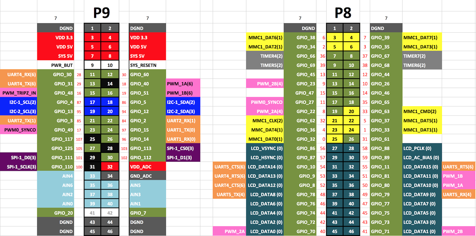
With the stuff I am working on, for example if you hook up the NO button to one of the IO pins. The difficulty is finding an appriate pin that is muxed correctly (details on other threads). But for this example if you choose: connector P9 pin 12, It is muxed to Mode 7, which is gpio1(28), which currently in my stuff maps to pin 32*1+28=60. So using my emulation of the functions, you can do things like:
pinMode(60, INPUT);
digitalRead(60);
But for a button type input, you typically want the IO pin to be either pulled-up or pulled-down. There are several ways to do this, you could use an external resistor like maybe 10K connected to +3.3v and to the IO pin, or you could try to enable the built-in PU resistor that is connected to that pin (ball). But to do that you need to figure out the address of the Mux associated with that pin and build up configuration information to build a device map overlay, that would tell that pin to enable the PU… More information in the threads I mentioned.
I attached my work in progress on mapping the GPIO pins and the default MUX settings for them. It is a work in progress so there may be some errors on it. The labels closest to the pins are the mode7 gpio names. Off to the sides I put the more interesting alternate signals. In parenthesis on the alternate signals are the modes for those signals. I colored the header pin to match the signal it is by default.
The red number next to the header pins is the kernel’s software pin number for that hardware pin. When you look in pinmux-pins and pins files you are looking for the red number. I’m also working on a reverse table. Listing the kernel pin numbers and the header pin that maps to that will have control register addresses as well as the pin I/O registers. Flipping through all the tables trying to link them together was making me want to scream.