Looking at this implies “chipname1,2,3” point to different locations. If its all the same chip try to remove the duplication.
1 Like
Hello @foxsquirrel ,
Okay. No issue. I think I found the culprit. My 9v supply should be no more/no less than 5v on the opposite side of the logic level translator.
I am using this one:
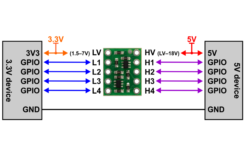
It can be found here: https://www.pololu.com/product/2595
Anyway, the motor driver datasheet states that I am incorrect. I should have used 5v supplies and not 9v, i.e. hence my motor driver is probably not goin’ to work with the current set up of 9v PWR and 9v GPIOs.
Seth
P.S. Unless the level translator used the 3.3v signals from the BBB, 9v GPIO levels may not be collective for the motor driver.
I will test. Thank you.
What are voltage are you supplying to the OPTO pin ?
I would not use 9V for the logic shifter. Use 5V.
If you use 9V (assuming the OPTO pin is 5V) then when the pin is high you have in effect a 4V reverse voltage on the opto-coupler led. I don’t know if it will be happy with that. You might blow the opto-coupler.
The DM332T is designed for 5V logic. You can use a higher voltage for the OPTO and DIR/EN/PUL pins but you will need to add extra resistors to stop the opto-coupler leds from blowing. See the datasheet
1 Like
I will use 5v. I am sure I can find something around here to handle the 5v supply needed.
I used to have this battery pack but it is missing… Aw!
Seth
P.S. I was not using the OPTO pin at all. I saw that in the datasheet that 5v is needed. Oops.
Just take the 5V from the BBB.
The 5V is not drving the motor, that is supplied by the VDC pin and can be anything upto 24V.
The 5V for the OPTO pin is purely the supply for the opto-couplers.
1 Like
Okay…I will test but later. I will return service once I test.
Seth
Okay,
So…
BBB (5v) to OPTO (driver)? Direct connection?
BBB GPIO pins (3.3v) to EN, DIR, PUL (driver)?
Outside of those ideas, I still need a 5v source for the level translator because of the BBB GPIO pins being 3.3v, right?
Seth
P.S. I have an older bench PSU I can test for making it 5v. This may come in handy. The only issue is that the bench supply PSU is iffy. I never really know what current I am at during voltage changes.
The PSU just goes blank on the DRO. So, I could be putting in 10A or 0.5A. I will not have a clue unless I test that too. Which is what I must have to do now. Argh. Okay, I will get on it.
BBB 5V to OPTO pin and 5V logic shifter
This may be odd…
Okay…so.
- Two 9v in series to power the motor driver.
- Bench Supply PSU for 5v to the logic level shifter.
- GPIO pins from the BBB to logic level shifter to the motor driver.
Testing now without the OPTO. I will report back.
Update
I will try the OPTO when I get back. Duty calls…
BBL!
you need to have 5V to the OPTO pin. It won’t work without it.
1 Like
Hahaha. No wonder I was having so much trouble.
Blah.
Seth
P.S. Thank you!
Hey Ben,
Seth here. Okay and A-Okay here. I am going to test tonight. It is late now but I will try anyway…
Updates on the way!
Seth
Update?
Okay…so…Argh first off. Secondly, hmm.
Okay so, this is what happens on my end so far.
- Plug in, boot, and scour the fs.
- Run source after wiring with power off…
- Once I run the source, the outputs stay as outputs on the BBB which denies me access to python3 scripting after handling
gpiod.hand C/C++ bindings.
a. This would not matter to me so much, i.e. as I can reboot and just run pure python3 files without having to issue the C/C++ files as output for GPIO while not being able to set them as input unless…
b. One has to not only release the chips and so on but one has to create them as input too for future usage.
c. Ben, I put the OPTO pin in the method… Oh.
I think whatever I am doing, nothing to this day, with the Stepper Driver so far creates me to know I can do it by blaming others only. That is okay. I can blame all day but in the end, it is me. I am doing the source directed at the BBB to handle GPIO and methods for driving Stepper Motors.
So, although this may seem too simplistic for you, do I need to alter the state of OPTO? I will alter OPTO in the meantime and return service (hopefully before my rant is read in public). Aw!
Ben,
I got the jitters so far!
So far, jitters only! That is something more than excitement!
Seth
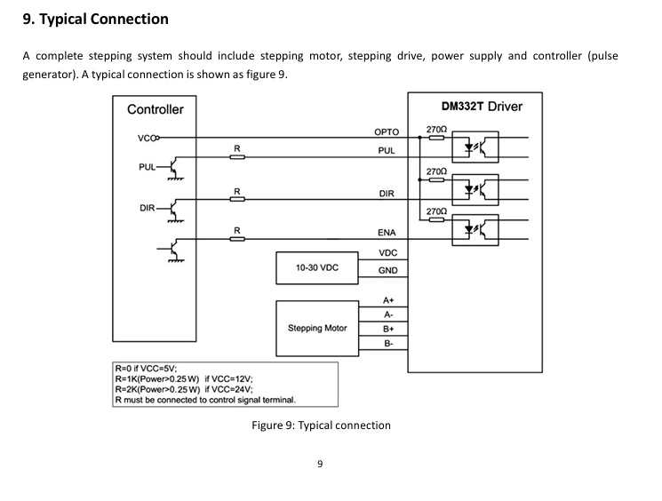
I see also on this particular stepper driver one would need to place a resistor of a specific ohm to handle 12v and/or 24v.
See photo below:
So, I will try with 12v once I get up and running again. My, as some know, PSU is outdated and a bit discriminating towards amperage and voltage. It seems my amperage output to the driver is lacking for now.
I will invest in a switching supply with one that has 5v output and 12v output.
Seth
P.S. In series, this resistor may need to supply additional protections against EMF. I have been unable to test thus far due to PSU and changes in the FS. I am trying to keep up and do things as beagleboard.org sees fit for now. Anyway, I will apply the 5v to the OPTO signal on this specific driver to handle motor movement. Do not give up just yet!
You only need the extra resistor if you are driving the control pins with something greater than 5V.
The control pins are isolated from the stepper motor driver using opto-couplers as shown in the diagram. There are internal resistors which are all that are required if you are driving the pins with 3V or 5V logic. If you are driving the pins with something higher (unlikely) then you need to add the extra resistor to prevent the opto led from blowing.
The supply for the motors is a completely different thing, and has no impact on the PUL/DIR/ENA signals.
In the above diagram VCC → OPTO is your mirco controller logic supply, so probably either 3.3V or 5V depending on micro. The optos will pull only 10’s of milliamps from this.
VDC is the supply for the stepper motor. This can be upto whatever the stepper module and motors can handle and would obivously need to supply amps, again depending on your motors.
2 Likes
Hello and Thank you Once Again,
I am starting to understand the datasheet a bit more. Thank you for the clarification.
Seth
P.S. I will attempt this effort soon again and again until completion. Lots to do and only so much time is a reasonable excuse for me (I guess). Anyway, thank you again and it will be done soon…