Seth here. Um, so with digital stepper motor drives, would I need to use PWM and GPIO or just GPIO?
The reason I am asking is because some individuals online are saying this and that…
Some others are just saying this or that…
Anyway, if it is up to me, I say PWM and GPIO but I would love to hear about what you think.
Seth
P.S. For instance, DM332T is a stepper driver I currently own. I was going to use it but I was “made” to believe that GPIO only was the method in which I use the BBB for controlling the motor driver (hence my odd insinuations and questioning). Send guidance!
It depends on your system.
The robustness of your drive controls.
Timing constraints.
So many options and so many choices, best solution is build and test.
Myself if the system would work fine with steppers I would gravitate toward GPIO for direction/motion controls. Your code would be much simpler to develop and maintain. This would also let your board focus on the main task of controlling the device and sending commands via UART control to an HMI like nextion for a very robust ui/ux.
Keep in mind every feature you add to the board increases realtime latency to the device being controlled.
First off, thank you for replying. Secondly, PWM is input for now. Blah…
So, I am without output as PWM on the Bookworm distro for the BBB. The only other board I have currently is the BBAI-64 which does have PWM access via overlays that get labeled in /boot/firmware/extlinux/extlinux.conf.
I looked in the am335x sections on the BeagleBoard-DeviceTrees and did not find anything of use for that specific chip which is on the BBB. I checked /include/ and /src/arm/.
My DM332T driver for stepper motors seems to be working but I am not getting any movement yet, i.e. not like before today or yesterday while attempting use case scenarios.
The motor driver uses PWM (Pulse) and GPIO (Direction and Enable) for controlling the drive.
When I said earlier that the gpioinfo command returned the output of the PWM in /dev/bone/pwm/* being input, I meant it. Is PWM on the am335x supposed to be input or is there something going on that has to do with the PWM efforts on the BBB?
Seth
P.S. If PWM is out of the question for the am335x on Bookworm with the DTS, okay. But why is it that the PWM peripherals need to be input to create this effort? No CLOCK, in the DTS is what I am guessing…
No issue. I am sure there is a reason. I can always resort to older models.
If you want positional accuracy you will not get that with PWM on its own. Not running software on Linux. With barebone software maybe.
Imagine this. You want to move 1000 steps. The PWM frequency is 1khz. Each step is 1ms. How do you stop on exactly 1000 steps with out going over ?
What if it is less ?
If you just want the motor to rotate and you don’t care about rotational position, yes a PWM signal will do that, with the speed being based on the frequency.
You could feed the PWM into a counter and count pulse and get that to interrupt you at the right time. Then you just need to make sure your interrupt latency is less than the step period. You could also use shift encoder somewhere on the output to feed your counter. This would be more accurate because it is measuring actual rotation. The PWM feeding a counter is fine as long as you don’t try to step to motor to fast , and careful with acceleration/deceleration to prevent undershoot/overshoot.
Using a GPIO pin to toggle the pulse pin is a much safer way to go. If one of your pulses is a bit longer than the last it doesn’t matter. If your program freezes for a second it does not matter. You are in full control of the pulses and how many pulses you write. It might not look pretty, the motor might be a bit jerky, but it should work.
With the PWM, are you sure you are not looking at the input capture pin for the module? I don’t know if they are seperate pins or muxed with the pwm outputs.
I am about to leave. Thank you for the consideration on this effort in my thinking and knowledge.
I appreciate the time. Also, okay about PWM and GPIO. I am starting learn more about how the combination of the two may or may not work as well as other methods with other peripherals.
If it goes over, okay. If it is under the maximum step(s) in this case, okay. The requirement would be a soft stop and a hard stop in the matter to handle length from a linear perspective and stoppage in case things got out of hand.
I have been unsuccessful with the toggling of the GPIO pin for PUL (pulse or PWM). I went through the DM332T short datasheet and found that PUL is definitely a PWM instance.
A PWM signal is just a signal that goes high and low. Toggling a GPIO signal is the same thing. A signal that goes high and low. With a hardware PWM signal the timing will be accurate and independent of program timings. With a software PWM using GPIO your duty cycle and frequency will have some jitter. But when moving a stepper motor the important thing is to count the pulses. If a high is 10us or 20us it doesn’t matter it will still be one pulse. As long as you don’t pulse the the GPIO pin faster than the limits it will work. If in doubt hook up a DSO and check your timings.
If doing it from Python I would be surprised if you go too fast.
cw/ccw/step. Your step would be just a plain old pulse that fits the requirements of your drive. It really needs an enable and some E stop mechanism too. For in the lab 3 gpio would be fine. Should be able to run a step pulse on a realtime core and that would be less demanding than doing an actual PWM. So much of this depends on the system dynamics. For example if you are designing an automatic barn door that moves not so fast you are more than likely going to have great success regardless of the method you chose.
Just use a pthread and while loop to drive a gpio pin and study that using a scope. You will see the “jitter” and the pulse dropping out when the speed of the loop is increased or when you add more pthreads to the mix.
GPIO * 3 is the “same” as using GPIO * 2 and PWM * 1.
So, instead of using PWM to control the frequency or travel and two GPIO pins for one way (CW) and then the other way (CCW), I would just use an extra GPIO pin since both PWM and GPIO are digital signals…
See, I figured since I could keep the PWM HIGH for longer, I could then control the other directions of linear travel with two, separate GPIO pins.
But, I am starting to understand more. I can leave the GPIO HIGH and then use the other two GPIO pins for traveling CW and CCW.
I am missing a bit of intelligence here. So, EN is to me an enable pin or a GPIO which stays on while the CW and CCW GPIO pins are commanded. Is this a fact? Is it a fact that EN stays HIGH to control the traverse CW and CCW of the other two GPIO pins for linear travel?
It is not that big of a deal if I do not conquer this exercise but I would like to understand more. So far, I have not come across instruction on EN (enable), PUL (?), and DIR (direction). I have seen some ideas floating around in Arduino worlds but they deal with 5v logic and less circuitry due to the lack of level shifters.
For instance, on the BBB, I have a logic level shifter. The level shifter handles 3.3v to 5v signals (PWR and GPIO pins) but then the GND pins need to be connected. I am trying to not use the 5v pins on the BBB.
This way, I can utilize 3.3v to 5v logic on the level shifter from a new source. The source is just a battery in this case. I think this is where I am finding error.
The PWR or battery in this case does not have GPIO pins and no way to communicate to the level shifter of the change…
Should this matter? I mean…
a. BBB (3.3v) to level shifter to Battery PWR
b. BBB (GND) to level shifter to Battery GND
c. BBB (GPIO pins) to level shifter to Stepper Driver
Does a - c work or is that a faulty communication error on my part?
Seth
P.S. I have some knowledge but for some reason, I am making some mistakes in either my thought processes after research and/or physical connections.
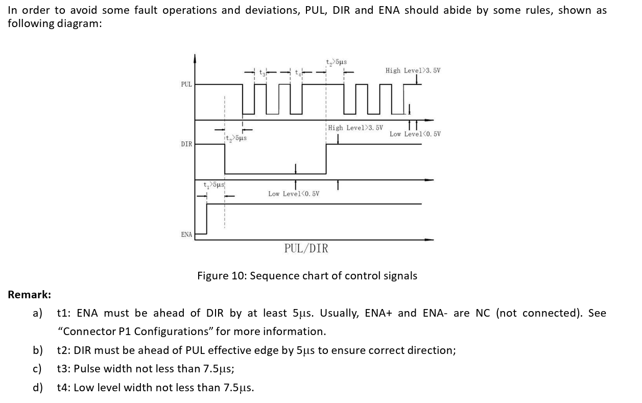
The PUL (pulse) pin is your stepping pin. 1 pulse is 1 step. Pulse for as many steps as you need.
The DIR pin is the direction of rotation. a high will rotate one direction, a low in the opposite direction.
The EN pin enables the output drivers. How you use this pin will depend on what you are using the motor for. If the output drivers are disabled, then the motor coils are no longer energised, meaning you will be able to easily turn the motor by hand. This is a problem if you are driving the Z axis of a 3D printer for example. If the coils are not left energised then gravity will gradually pull the print head down. However if you are driving a simple 2 wheeled robot on a flat surface, then if you are not moving you could disable the drivers to reduce power consumption and heat in the motors.
It really depends on what the motors are attached to and how you are using them.
If we are talking about the DM332T tepper driver then no, that is wrong.
The PWR pin is the supply for your stepper motors upto a max of 24V
You level shifters need to be connected to the 3.3V and 5V supply.
The OPTO pin is connected to the anode of the optocoupler. There is are internal current limiting resistors so this pin can be connected to 5V.
@benedict.hewson … Yes, I use the DM332T. I have the datasheet. The battery PWR I was discussing was the 5v source and not my bench supply and/or 12vdc supply.
I was going to use the batteries for a 5v source… I have a smaller battery holder that can get around that voltage.
I will retry with your ideas and see how far I get. EN is enable (GPIO). Dir is a GPIO pin that controls the rotation (left or right) for the motor. The PUL pin is another GPIO that controls the stepping and has to do with the amount of HIGH or LOW of the GPIO for it being “on”.
So, in theory, I cannot move left without stepping and it being enabled. Okay. So, enable, step, and then dictate the direction.
Or…should I use enable, dir, and then step in that order of GPIO pins being used?
Got it! I got this to work once before this time. I thought I understood what needed to happen but without the older source and specific hardware, I have been wrong so far. Off to test and now!
I should mention that I am using the BBB and not a different SBC here…
Here is the command gpioinfo.
gpiochip2 - 32 lines:
        line   0:     "P9_15B"       unused   input  active-high
        line   1:      "P8_18"      "P8_18"   input  active-high [used]
        line   2:       "P8_7"       unused  output  active-high
        line   3:       "P8_8"       unused  output  active-high
        line   4:      "P8_10"       unused  output  active-high
line 2 - 4 are what are being used as GPIO pins for this motor. I can show various forms of source is necessary but the pins were there in /sys/class/gpio/* and then disappeared. Poof…gone. ?
Seth
P.S. Should I use another board or try a different image? I got confounded tremendously here with the way the pins abruptly were removed with trying to use config-pin (I am guessing this is the case).
Here is a drive typical of what we use, this model was the first on a search and we have never used this model and do not endorse it, this is for information only.
Look at the spec and you will see the requirements for the control, this is typical of a real world application.
When building a control you might have to use c instead of python. Best practice would be a mutex hard lock on the cc/ccw gpio pins, not sure if python has mutex or semaphores. Most don’t bother doing it, however the ARM boards can perform trajectory calculations much faster than years ago so, issues, in theory are possible.
// Simple gpiod example of toggling a LED connected to a gpio line from
// the BeagleBone Black and Relay Cape.
// Exits with or without CTRL-C.

// This source can be found here: https://github.com/tranter/blogs/blob/master/gpio/part9/example.c
// It has been changed by me, Seth, to handle the Relay Cape and the BBB Linux based SiP SBC.

// kernel: 5.10.168-ti-r72
// image : BeagleBoard.org Debian Bookworm IoT Image 2023-10-07

// type gpioinfo and look for this line: line 20: "P9_41B" "relay1" output active-high [used]
// That line shows us the info. we need to make an educated decision on what fd we will use, i.e. relay1.
// We will also need to locate which chipname is being utilized. For instance: gpiochip0 - 32 lines:

// #include <linux/gpio>

#include <gpiod.h>
#include <stdio.h>
#include <unistd.h>

int main(int argc, char **argv)
{
    const char *chipname1 = "gpiochip2";
    const char *chipname2 = "gpiochip2";
    const char *chipname3 = "gpiochip2";
    struct gpiod_chip *chip1;
    struct gpiod_chip *chip2;
    struct gpiod_chip *chip3;
    struct gpiod_line *lineEN;
    struct gpiod_line *linePUL;
    struct gpiod_line *lineDIR;

    int i, ret1, ret2, ret3;

    // Open GPIO chips
    chip1 = gpiod_chip_open_by_name(chipname1);
    chip2 = gpiod_chip_open_by_name(chipname2);
    chip3 = gpiod_chip_open_by_name(chipname3);
    if (!chip1) {
        perror("Failed to open chip1\n");
        return 1;
    }
    else if (!chip2) {
        perror("Failed to open chip2\n");
        return 1;
    }
    else if (!chip3) {
        perror("Failed to open chip3\n");
        return 1;
    }

    // Open GPIO lines
    lineEN = gpiod_chip_get_line(chip1, 2);
    linePUL = gpiod_chip_get_line(chip2, 3);
    lineDIR = gpiod_chip_get_line(chip3, 4);
    if (!lineEN) {
        perror("Get lines failed\n");
        return 1;
    }
    else if (!linePUL) {
        perror("Get lines failed\n");
        return 1;
    }
    else if (!lineDIR) {
        perror("Get lines failed\n");
        return 1;
    }

    // Open GPIO lines for output
    ret1 = gpiod_line_request_output(lineEN, "p8.7", 0);
    ret2 = gpiod_line_request_output(linePUL, "p8.8", 0);
    ret3 = gpiod_line_request_output(lineDIR, "p8.10", 0);
    if (ret1 < 0) {
        perror("Request line as output failed\n");
        return 1;
    }
    else if (ret2 < 0) {
        perror("Output line failed...\n");
        return 1;
    }
    else if (ret3 < 0) {
        perror("Output line failed!\n");
        return 1;
    }

    // Run the stepper motor(s)...
    ret1 = gpiod_line_set_value(lineEN, 1);
    i = 0;
    while (true) {
        ret2 = gpiod_line_set_value(linePUL, (i & 1) != 0);
        ret3 = gpiod_line_set_value(lineDIR, (i & 1) != 0);
        if (ret2 < 0) {
            perror("Set line output failed\n");
            return 1;
        }
        else if (ret3 < 0) {
            perror("Set up failed once again...\n");
            return 1;
        }
        usleep(1000000);
        i++;
    }

    // Release lines and chip
    gpiod_line_release(lineEN);
    gpiod_line_release(linePUL);
    gpiod_line_release(lineDIR);
    gpiod_chip_close(chip1);
    gpiod_chip_close(chip2);
    gpiod_chip_close(chip3);
    return 0;
}
That is what source I am currently using. My GPIO pins disappeared but are listed in gpioinfo.
The /sys/class/gpio/* files have ceased to be there for me… So, I am trying gpiod.h instead.
Seth
P.S. It compiles without error but does nothing. I think something is either wrong with the motor or my supply for PWR to the motor. I will keep it up!
I checked the main battery, 12vdc, and it shows above 12v. I checked my 9v battery for the translation of the logic level translator and it is “juiced up.”