Hi All,
Currently, I am working on an open gigabit Ethernet cap for the pocket beagle 2 to leverage the TSN feature that the AM632 is providing and make it accessible openly for everyone.
The ultimate goal is to provide AVB/Milan pipewire on this mini Linux box. One colleague and I are the person behind this Milan/Pipewire, you can get additional information there: https://kebag-logic.com/. I have the Ethernet cap almost ready, I will share it on GitHub very soon with an open licence.
But for the RGMII to work, I need to match the flight time and length of the RGMII lanes. I cannot view the exact size of for the RGMII2 Lanes needed to have a working Gigabit network interface. I tried with Altium 365 online, but the distance was accounting for the additional shared lane. I use Kicad because it is free and I cannot open the .brd file from the github repo.
Has anyone Altium an can exacty measure, or even better, if someone from the HW dev team knows something about that please give me the answer.
Hey I also have a similar plan for my PocketBeagle 2 involving Ethernet and HDMI. Not sure if HDMI could work but I am glad to see your thread. I have access to PCB design softwares from Altium/Cadence and can help with finding the lengths of RGMII traces. I believe .BRD files are generated from Cadence Allegro
I was able to extract the trace lengths of the nets as requested. The lengths are directly reported by Allegro:
RGMII2 SIGNALS
CPU BALLS
Length in mils
RD0
AE23
P1.27 - 2177.03mils
RD1
AB20
P1.25 - 1985.47mils (not exact due to T-branch to U11)
RD2
AC21
P1.23 - 2127.61mils (not exact due to T-branch to U11)
RD3
AE22
P1.21 - 2158.49mils (not exact due to T-branch to U11)
RX_CLK
AD23
P1.34 - 2204.81mils (not exact due to T-branch to U11)
RX_CTRL
AD22
P1.19 - 2249.93mils (not exact due to T-branch to U11)
TD0
Y18(netname=D20)
P1.04A - 1182.32mils
TD1
AA18(netname=A13)
P2.31A - 1991.72mils
TD2 (2 possibilities)
AD21
P1.12A / P2.10 - 785.48mils
TD3 (2 possibilities)
AC20
P1.06A / P2.19 - 328.86mils
TX_CLK
AE21
P1.35 - 2442.23mils
TX_CTRL
AA19
P1.02A - 2925.95mils
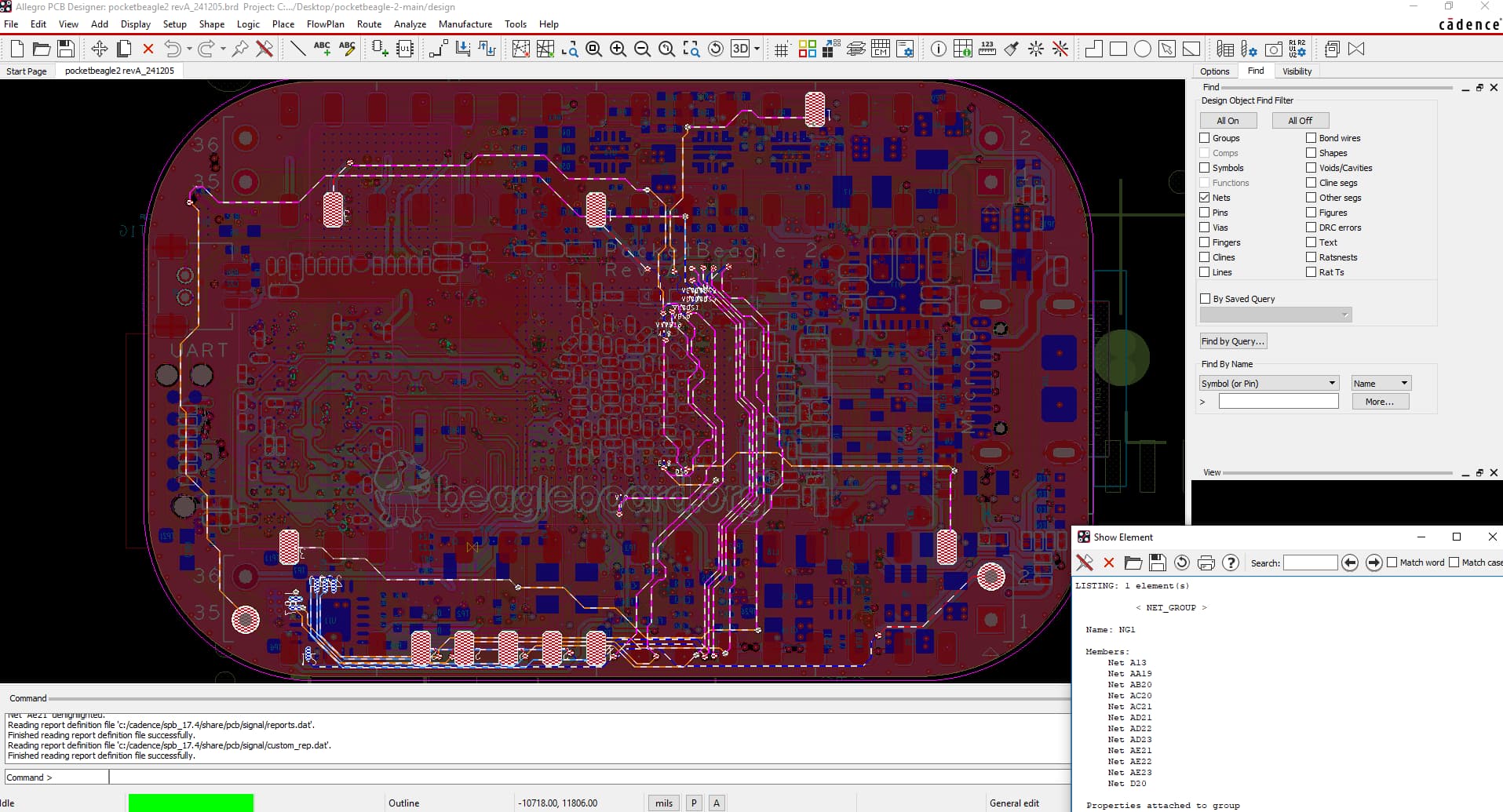
However by visual inspection, I saw that there are 5 nets that have a T-branch so instead of these RGMII traces going from SoC directly to P1/P2 Header, it is like SoC->Header->U11(MSPM0). Those are the highlighted 5 pads which are contiguous in the attached image which means the true time of arrival (electrical length) or for the signal to arrive from SoC to Header is shorter than the physical length reported by the software.
Signal integrity not so much but possibly data integrity can be affected. The lengths of all clk/data lines are kept roughly the same (length matched) so that your data arrives at the same time or has no noticeable phase difference. I think it would be a good idea to know the the exact lengths so that you can compensate for length mismatch in your own Ethernet Cap to get a “Right the First Time” HW design. Give me a few days and I will get back with the exact lengths. I will take a look at your KiCAD design as well in the meanwhile.
Here are the exact lengths of the RGMII lines after removal of T-branch traces(CLINES in Allegro). Small correction, T-branch occurs in AE23 instead of AD23 which I had reported earlier in the thread.
RGMII2 SIGNALS
CPU BALLS
Length (mils)
RD0
AE23
1808.5
RD1
AB20
1520.17
RD2
AC21
1511.44
RD3
AE22
1459.68
RX_CLK
AD23
2204.81
RX_CTRL
AD22
1350.87
TD0
Y18(netname=D20)
1182.32
TD1
AA18(netname=A13)
1991.72
TD2 (2 possibilities)
AD21
785.48
TD3 (2 possibilities)
AC20
328.86
TX_CLK
AE21
2442.23
TX_CTRL
AA19
2925.95
I started following the Github repository of the Ethernet cap design. Let me know if you need help there as well
My idea was to use this as an audio TSN box (based on Milan/AVB or pure AVB).
So there are 2 PMODs attached to the MCASP2 now. I do not really need them I can use the UAC Audio USB compliant interface providing 4x4 @ 48kHz.
So long story short, and if you’d like, we can remove them .
Please don’t hesitate to contact me on GitHub or DM me here if you need.
Hey Its not finished, unfortunately i have not completed the bom, and did not produced the pcb. but Now that someone is interested, i ll put some effort.
Hey guys can we arrange a discord/zoom chat, to see how we could contribute in the board and delegate some tasks so we could a have finished board in the next couple months? I also want to have a discussion regarding other capabilities of RGMII which I don’t fully understand/know how to implement on my own.
I tried to contact you but could not get any answer from you via DM, please let me know if you have time someday to answer so I can discuss with you for the soft part.