When I cat in_temp0_scale I get the scaler of 250 but when I cat in_temp0_raw it returns 0. Is there some init process required to return the temperature reading? I’ve checked for using the AD7271 ADC Linux driver and I’ve not found any…
I have the LP-MSPM0C1104 and I don’t know if that is the same as what is used with that board. However, it takes CCS20 and a usb cable to program it, how is that chip placed, is it external to the SoC or or inside? Most of this is too tightly integrated with sysconfig so without that file, original .sysconfg that was used for board bring up you might just be confined to what ever it is pre-configured for.
@foxsquirrel
the MSPM0 is the ‘L’ version, it is located external to the SOC
looks like it will use I2C for programming.
there are documents in TIs site, but i was hoping not having to reinvent the wheel
the I2C address is 0x48, but i have yet to see any register mapping of the device
doing:
cat /sys/class/firmware/mspm0l1105/status
idle
not sure if that means the mpu is not running or this is for programming
update:
the mspm0 is already programmed, reading AIN0 works, floating reads 1980 ish and 2 ish when grounded.
It might take more than i2c to program it, the board I have is using the usb to xps110 debug probe chip to control the programming. Does the board have any exposed pads or connector for programming it.?
nope,
the mpsm0 contains a BSL and uses I2C or UART for programming. there are some reset llines, not sure how to use them. the link provided earlier seems to have an app that might do the programming when supplied a .hex.
being the AINx work, i’m not going to mess with it.
Here are instructions to flash mspm0 firmware. I am only going to put the CLI instructions here, since well, they are probably much more relevant in case of mspm0
Download bb-imager-rs latest version. Currently that is v0.0.3:
wget https://openbeagle.org/api/v4/projects/832/packages/generic/bb-imager-cli/0.0.3/bb-imager-cli-aarch64-unknown-linux-gnu.tar.xz
tar -xvf bb-imager-cli-aarch64-unknown-linux-gnu.tar.xz
cd usr/bin
Download the firmware from here or well, just any Ti-TXT or iHex firmware should work.
Just keep in mind that if you flash the mspm0, the eeprom with serial number and everything is gone. The eeprom is emulated on the mspm0 so if you use a different firmware, that functionality is gone.
Ahh, so bb-imager-cli can actually preserve EEPROM contents. You just need to remove the --no-eeprom flag. I thought @amf99 was trying to flash a firmware without EEPROM emulation.
Note: it does require that you are going from an EEPROM firmware to another EEPROM firmware.
uniflash is a ti application for programming the chip - I’ll need to read the documentation to see if it can program over i2c or uart. IIRC you need to take care not to ovewrite part of the flash - it has bits that are important for the BROM, e.g. if certain bits aren’t set, it locks down the M0+ hard …
And checking up on my notes, pyocd won’t work - it uses CMSIS-DAP to talk to the M0+ (or any other arm target) this is what the programming chip on the launch pad has installed. On the PocketBeagle 2 - as the M0+ is wired direct into the CPU, there is no CMSIS-DAP interface. This is a pity, as pyocd was very good at listing what is in the flash, and the DFP*.pack is very useful - as it says what you can write, and what you shouldn’t write. Its worth reading up on how the M0+ boots - as some of the bytes in the read only section are critical, at which interfaces are enabled. If you read up on the what the bootrom does on the M0+, yes it reads like it can be programmed over i2c - but alas its not something I’m familiar with. AM not sure if the TI Uniflash tool works over i2c - I may fire it up to check on one of my M0+ boards …
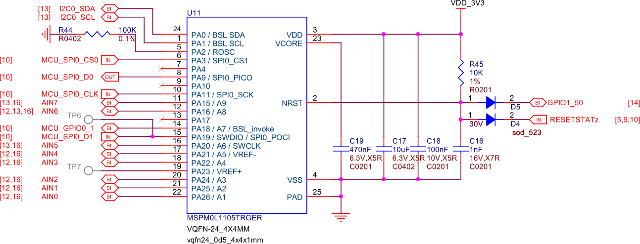
Yawn can’t sleep - so digging deeper into the schematics on https://docs.beagle.cc/boards/pocketbeagle-2/03-design-and-specifications.html and the mspm0+ is the chip MSPM0L1105TRGER a VQFN24 - so very few pins. the two wire programming is on pins PA19&20 - goes to MCU_SPIO_D1 and AIN5 … haven’t worked out where they go.
So looks very possible you can only use I2C to program that chip.
And following through to where the two wire mspm0+ connections go, its mainly SWCLK and SWDIO - and maybe BSL_invoke (to push the MSPM0+ into a different boot mode) : MSPM0+ pin out
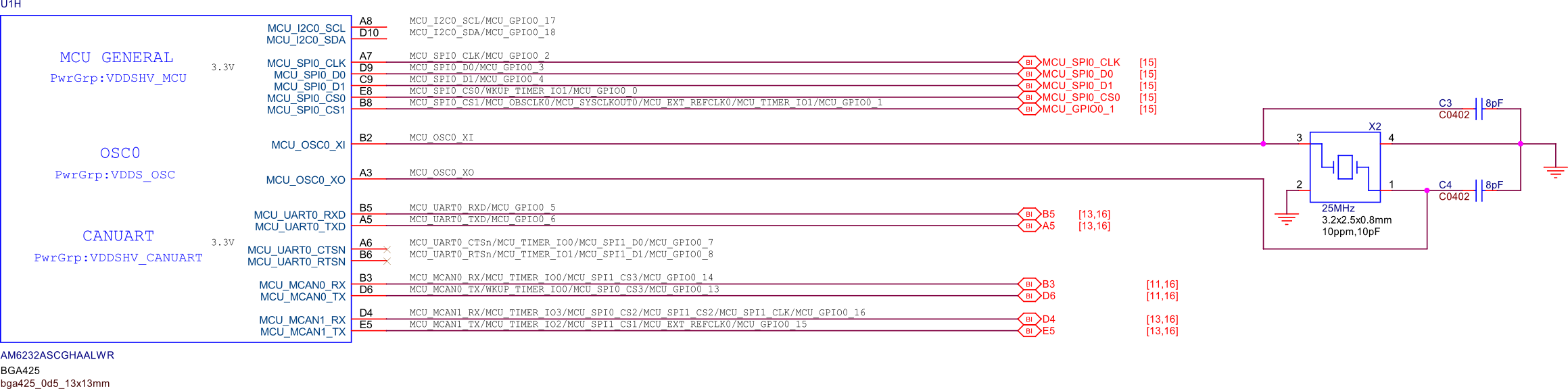
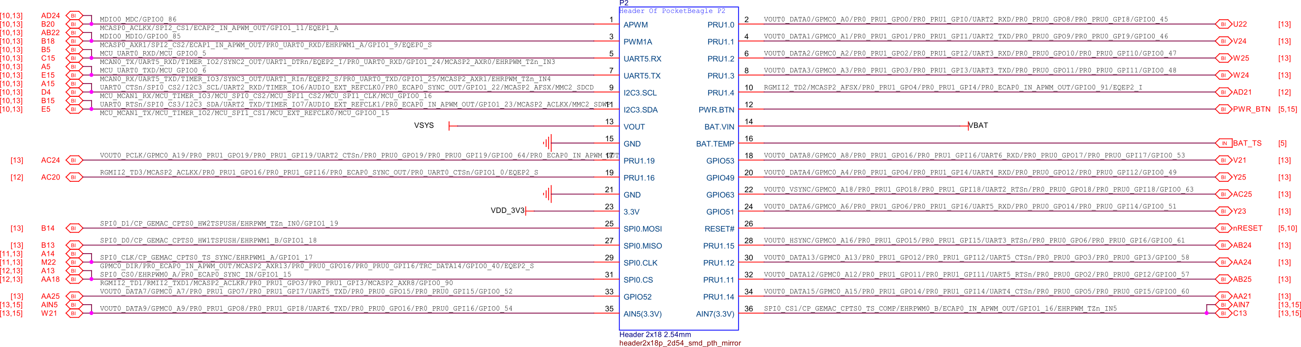
Most seem to go to the main CPU here: AM6232 pin out. The clock seems to go to the P2 header P2 header - which is a tad annoying, as looks like you can’t do the clock from the main CPU.
Should be able to get SWDIO and SWCLK on P2 header and TP6, which means you may be able to program the MSPM0+ from an external programming device.
BSL_invoke you seem to be able to toggle from the CPU - sothat may be worth setting, to force the MSPM0_ into a different boot mode.
Anyway looks like using two wire to program the MSPM0+ isn’t easy - so yes looks like the I2C is the main interface you can use. So following the link that was posted above.