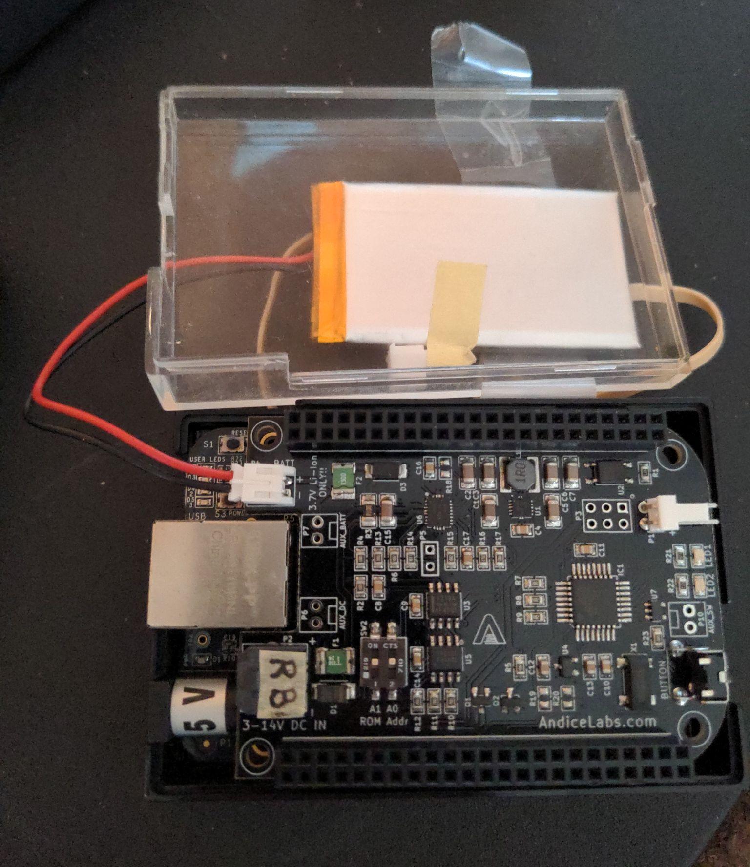
The charge port for the board is a Molex MicroFit (2 circuit) connector, and I am not supposed to use the standard 5V connector on the BBB. I already have a new battery connected to the JST port.
So, I can acquire a Microfit cable but then I have to somehow connect the other end to maybe a USB or wall plug, something like that. So I would have to splice my own cable. I talked to Molex about it and they didn’t have any specific products nor recommend trying.
AndiceLabs is no more, so I would ask them but I can’t.
Does anyone else have experience with this power cape, what did you use for a power supply? Did you create your own cable?
Or if I were to buy a USB header for the opposite end of the microfit cable, would it work? If I crimp my own cable, what should I take note of?
Will I fry the cape if I plug in the 5V power while I wait to figure this out?
Well it isn’t much, but from analyzing the old site:
First of all, it’s worth noting that (according to elinux.org) the cape is apparently not completely libre, so I doubt it would work on a libre kernel…
The exact connector (“crimp housing”) is 2 circuit Micro-Fit 3.0 (part # 43645-0200) and the port on the Power Cape is part # 43650-0203
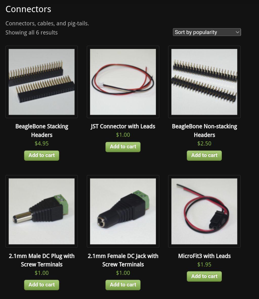
The store merch gives the impression that customers will be crimping their own connections
The size of the wires sold was 6 inch long, 24 gauge, so what I need to look for is 24 guage wires (24 AWG)
The store sold a 2.1 mm DC connector you can crimp to the other end of the MicroFit3 cable, this appears to be the same dimensions as used on the BBB main board (5.5mm diameter outside, 2.2 diameter inside). The best voltage for maximum efficiency is 5V
I see soldering in my future (ugh)
The Wires:
Obtaining the required voltage depends not so much on the AWG wire guage but what it’s connected to. Electricity 101
You can browse here for Micro-Fit supplies where I am avoiding at least some of the crimping. Molex won’t build you a custom cable unless you are ordering large quantities.
I am iffy about those pre-assembled cables because the guage (AWG) on them 18 and that is not conformant to USB specs. Hmm…
Aha! Part 145132-0210 uses 20 guage wire. Any of the 145132 series will theoretically fit a USB plug header.
24 guage wire should work but I can’t find it.
Even though I can only find 20 AWG wires, it appears that shops selling Micro-Fit terminals that fit this thickness are rated for 20-24 AWG, so they’d be the same terminals anyway. Also, I see shops USB cables exclusively for fast charging using 20 AWG.
The thickness of 20 AWG means I can carry a good voltage for longer cables.
The USB plug assembly:
There are YouTube videos that show how to make your own USB cables like this one and this one
You can ignore the green and white data cables, stick to the red and black wires but solder them to the correct places, and do not allow them to touch.
USB specs use 28 to 20 AWG for the red and black power wires, so a 20 AWG cable is enough, but the 24 AWG cable is fine too.
Crimping tools are way out of my low, low budget of $5 so it’s up to me to solder. (Type-A looks like the easiest by the way!) Molex only seems to sell PCB headers for USB, look for something like this called a usb cable mount
The cape’s maximum charge current is 1A. The USB header’s max is 1.5A. And the Micro-Fit port is 8.5A. So, current is sufficient.
The USB standard for all USB cables is 5V.
Don’t waste time with USB 3.0, all you need is the red and black wires so a 2.0 connector is perfect.
I have no idea what I’m doing. My attempts might fail. Additional troubleshooting info (to ensure that it’s not the fault of a bad or poorly crimped cable)
Will charge even after BBB is powered down
Stops charging after 3 hours: “There is a safety timer function integrated into the charge controller and it’s set for 3 hours. It can be changed with a resistor value (see schematics for details). An alternative is to monitor the battery voltage and current in software and toggle the “charger enable” bit in the AVR control register. This will restart the charge cycle.”
It is built to run with a 3.7V battery (like the one I have pictured above!)
over-voltage and reverse-polarity protection on both battery and DC input.
There are firmware updates available and you can edit your own scripts
Trivia: Only works with 6V solar panels, anything higher is lost as heat (if anyone wanted to know)
Trivia: The cape provides RTC time keeping function (hwclock)
“If a battery is drained below 3V, the charger will use a low-current “trickle” until the voltage recovers above 3V. Once battery voltage rises above 3V, normal charging will begin.”
“By default, a “DC power good” event will cause the Power Cape to power to the BeagleBone. This is useful in a number of scenarios but also emulates the standard BeagleBone behavior of turning on when a DC source is applied. However, if the cape has no power (battery) prior to this it usually won’t turn on when DC power is applied.”
“There is protection on the DC input that will clamp the input at 15V and potentially activate a PTC fuse. The charger will be disabled below roughly 4.2V and the input will automatically switch to the battery (if present).”
I also gathered from the old forum that: “the biggest battery that could be theoretically charged from empty with a safety timer and no software intervention would be around 10Ah. Software can monitor the battery voltage and current via the INA219 and can reset the charger by toggling CE through the AVR. A reset of the charger will reset the charge cycle. The cape charges a battery at its set current until the battery voltage hits 4.2V. Then, it holds this voltage until the current drops to 1/10 of the max rate (so, 100mA in the 1A case) which terminates the charge. The safety timer is just a “maximum charge time” that prevents the charger from over-charging a bad battery. IMO, the safety timer and the thermistor become more important the closer your charging rate gets to the limits of the battery.”
Will I fry the cape if I plug in the 5V power while I wait to figure this out?
At least one thing I feel more reassured about, is that I can plug in to the 5V DC on the main board, it just won’t power the cape. I think. Also, the cape is protected from overvoltage. But I wouldn’t want to try plugging in both 5V DC, so I’ll tape over the main board one when I get my cable made.
It gets a lot of hits, output, when I look up powercape andice labs beaglebone black. One thing, esp, that I found was this link:
https://elinux.org/AndiceLabs:PowerCape
Seth
P.S. It seems reassuring that it is in the elinux.org file system. Anyway, I wish you the best of luck. Oh and the bbb.io persons have another PowerCape made and I am still trying to figure out what exactly I can do w/ it. I know there is 3.3v and 5v on it but…
Do I power the BBB w/ it?
Do I power my other devices w/ it?
I am still in the dark w/ the PowerCape from GHI or Seeed or whomever produces it now.
Sort of new, fits snug! I think it is a better prototype than the older model in question. Anyway, I am still learning the ins and outs of it all. I can probably stick the ServoCape on it and power it by the PowerCape. Maybe?
Seth
P.S. The site for the Andice Labs Power Cape is no more, e.g. on the Element 14 site. It used to have some strong followers. I could not find it just now when searching via their Element 14 site.
As long as you use male-to-female stacking headers, you should be able to physically stack as many capes as you want, but I imagine that every new cape requires more power. Not sure what the limits are.
I don’t know about all that, but, if the battery cape is supported without any software required, then I think the Power Cape should too, they’re not that different.
P.S. It is a bit odd to me for some reason. I am sure the people that put in the time and work ethic to produce made it that way for a reason. I am still wondering about it!
Has an INA219 on battery input to allow monitoring of battery voltage and current from the BeagleBone.
Does not consume GPIO. Only uses two addresses on the I2C2 bus: one for the AVR and one for the INA219.
The reason i ask is I now have two copies of Derek Molloy’s Exploring Beagle Bone. Both editions out of date in just a few years. Other books too. Try installing an older version of the OS and do an apt-get update and the web links that at least used to give the most recent drivers for that version are gone.
A really good example is this cape which I bought this spring. Amazing product. Super good support: MFM Hard Disk Emulator using BBB
Running an older version of the BBB OS. I asked why he hadn’t updated. Simple answer was too much work for no benefit. Now that’s a dedicated product and the disk image is functional as is. So who cares. Although I did install SAMBA and can link to it from my Windows System. Was able to get that working.
For a battery backed up power supply with current and voltage monitoring I don’t think I’d continue to create updates for little financial return if the OS was a moving target and so I’d probably discontinue my product too. Which is why my Replicape and touch screen are also sitting in box now.
For that to be the case with the Power Cape and the Battery Cape, which are fairly simple electrical devices, there would have to be (userspace) drivers for them that the OS would have to support.
I think the 2 things you mentioned use the Linux kernel? https://www.kernel.org/doc/html/v5.4/i2c/dev-interface.html
In other words, it isn’t AndiceLabs that is contributing towards I2C development, merely using its cross-platform functionality same as other components like Molex, USB, etc.
Extra software configuration is supported in this Power Cape, but not required. I question whether updates are even needed. Would you need updates for your laptop charger?
