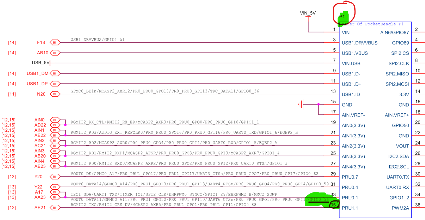
I am working with the PocketBealge2 and I am trying to run one of the examples for the GPIO pins. I have uploaded the Debian 12 v6.12.x IoT image from the imaging tool. I didn’t configure anything else just started the beagleboard and opened the VsCode server to try the example. While running it I checked the status of the pin with
gpioinfo gpiochip2 | grep P1.35
and the result I am getting is:
line 88: "P1.35" "toggle1.c" output active-high [used]
What I am understanding from this, is that the Pin is being adressed correctly and being used by my program but the Pin is physically still not changed. I have hooked up an LED to test and it doesn’t turn on even though the pin is active-high. I have tested hooking up an oscilloscope on the pin and there was no change in woltage level whatsoever.
Am I doing something wrong or have I forgotten something??
This guide from TI e2e should set you in the right direction
For your schematic reference look at pages 32 and 33 here pocketbeagle-2.pdf.
So for example, from looking at the schematics in pocketbeagle-2.pdf, we see P1_35 is GPIO0_56. You then configure GPIO0_56 following that TI e2e FAQ guide.
EDIT, it looks like you can skip over a lot of the work described above..
Much of the pin muxing has already been figured out by beagle. You don’t need to be digging in and doing things the slow hard way as with the TI E2E method. In k3-am62-pocketbeagle2-pinmux.dtsi, there is a GPIO pinmux configuration for each GPIO. You’ll just need to setup an overlay that uses these configs. I’d assume there is probably a guide in the PB2 documentation on this. Looking at the few provided overlays, I found this overlay to have best example use, it is kinda eh.
You could still go with doing things the hard way, and go with not using the per figured out muxing in k3-am62-pocketbeagle2-pinmux.dtsi.
P.S. I got a PB2 on hand to test. I was just wondering…
Are overlays needed to handle GPIO and etc. with the PB2?
Is this an overwhelming adventure from the personnel at beagleboard.org?
Should “I” expect to start handling peripheral access via the DTS for now on?
Anyway, I will get back to posting sooner or later. I am just trying to wrap my head around what is currently done and how… Off to read more.
Update Here…
I tried the regular style of command line interfacing of GPIO pins with libgpiod-dev/gpiod. Without being to update/upgrade, I cannot use the interface on the command line (I think). I tried internal LEDs and tried some basic operations with an external output. Anyway, I will keep trying.
Try this script. Make sure to replace “$SCRIPT_DIR/our-custom-overlay.dtso” with the path to PB2-easy_p1_35.dtso.
#!/bin/bash
# Set SCRIPT_DIR to the absolute path of the script's directory
SCRIPT_DIR="$(cd "$(dirname "$0")" && pwd)"

# Define source and destination directories
DTB_SRC="$SCRIPT_DIR/BeagleBoard-DeviceTrees"

# Remove the target directory if it exists
rm -rf "$DTB_SRC"
# Clone the repository into the specified directory
git clone --branch v6.12.x-Beagle --single-branch https://github.com/beagleboard/BeagleBoard-DeviceTrees.git "$DTB_SRC"

# Copy the overlay file
cp "$SCRIPT_DIR/our-custom-overlay.dtso" "$DTB_SRC/src/arm64/overlays/"

# Build the device trees
make -C "$DTB_SRC" -f Makefile clean
make -C "$DTB_SRC" -f Makefile

# Install device tree stuff
sudo make -C "$DTB_SRC" -f Makefile install_arm64
I tried that cript but it seems like my PB2 isn’t connected to the internet because it fails cloning the repository and I get this error message:
Cloning into '/home/debian/BeagleBoard-DeviceTrees'...
fatal: unable to access 'https://github.com/beagleboard/BeagleBoard-DeviceTrees.git/': Could not resolve host: github.com
cp: cannot create regular file '/home/debian/BeagleBoard-DeviceTrees/src/arm64/overlays/': No such file or directory
make: *** /home/debian/BeagleBoard-DeviceTrees: No such file or directory.  Stop.
make: *** /home/debian/BeagleBoard-DeviceTrees: No such file or directory.  Stop.
make: *** /home/debian/BeagleBoard-DeviceTrees: No such file or directory.  Stop.
I tried connecting it by following this "tutorial” :
Run git clone --branch v6.12.x-Beagle --single-branch https://github.com/beagleboard/BeagleBoard-DeviceTrees.git "$DTB_SRC" on your dev machine. Copy the folder over to your beaglebone somehow. Edit the script so that $DTB_SRC points to whatever location you placed the folder at.
#!/bin/bash
# Set SCRIPT_DIR to the absolute path of the script's directory
SCRIPT_DIR="$(cd "$(dirname "$0")" && pwd)"

# Define source and destination directories
DTB_SRC="<EDIT THIS PATH TO POINT TO SPOT WHERE YOU COPIED YOUR MANUAL CLONE TO>"

# Copy the overlay file
cp "$SCRIPT_DIR/our-custom-overlay.dtso" "$DTB_SRC/src/arm64/overlays/"

# Build the device trees
make -C "$DTB_SRC" -f Makefile clean
make -C "$DTB_SRC" -f Makefile

# Install device tree stuff
sudo make -C "$DTB_SRC" -f Makefile install_arm64
I managed to write an overlay for the board. I couldn’t seem to load the k3-headers, so I used the hex values for the BALL configuration instead of AM62X_IOPAD().
I implemented 3 GPIOs for testing purposes. Two of which I connected buttons to and one the other is connected to an LED. Even though all three are configured as inputs, the led GPIO can be controlled as either in -or output with libgpiod. This is the overlay I came up with: