I think I managed to burn out the TPS65217 on the BBB using a custom cape that I designed. The cape has a DCDC switching regulator that I’m using to drop a 12V supply down to 5V for the beagle bone. I have the 5V from that switching regulator connected to pins P9.6 and P9.5.
I’ve now had two BBBs fail while powering them from the board. I left both on for a couple of days, and at some point the BBB just died. After that, the BBB don’t boot at all, even with the cape unplugged.
When I apply 5V from a benchtop supply to P9.6, I only see 1.1V on P9.7 (system 5V).
If I hit the power button (S3), then the voltage on P9.7 will jump up to around 2.5V before falling back to 1.1V over around 20s.
I’m not sure what’s going on here, since the power supply I’m using looks pretty clean to me. It’s an average of 5.14V with max 150mVpp noise. It’s rated to 2A current draw. Switching frequency is 150kHz.
Does anyone have any idea what might be happening here? Any ideas about what I should try next?
It is likely a transient voltage spike that can come out of your switcher.
The BBB does not turn on it’s power supply until it thinks the incoming voltage is stable, which means that your 12V to 5V switcher is starting up without a load. If it overshoots badly in that start-up period, it could kill something. Or if it overshoots when the BBB load is finally applied
I would start by repetitively starting up your 12V to 5V switcher, without a load on it, and watching what the output does on a storage (memory) oscilloscope, so that you can see the worst case startup condition. Then repetitively add a load equal to the BBB and all its input capacitance, and watch what happens.
What were you controlling with the BBB/Cape? Things like relays or stepper motors generate inductive spikes that can easily kill semiconductors, if the spikes are not managed correctly.
I actually had a couple of relays attached to this without flyback diodes,
so that may be causing voltage spikes on the 5V input line.
I'll take a look at the un-loaded startup of my regulator tomorrow and see
how it looks.
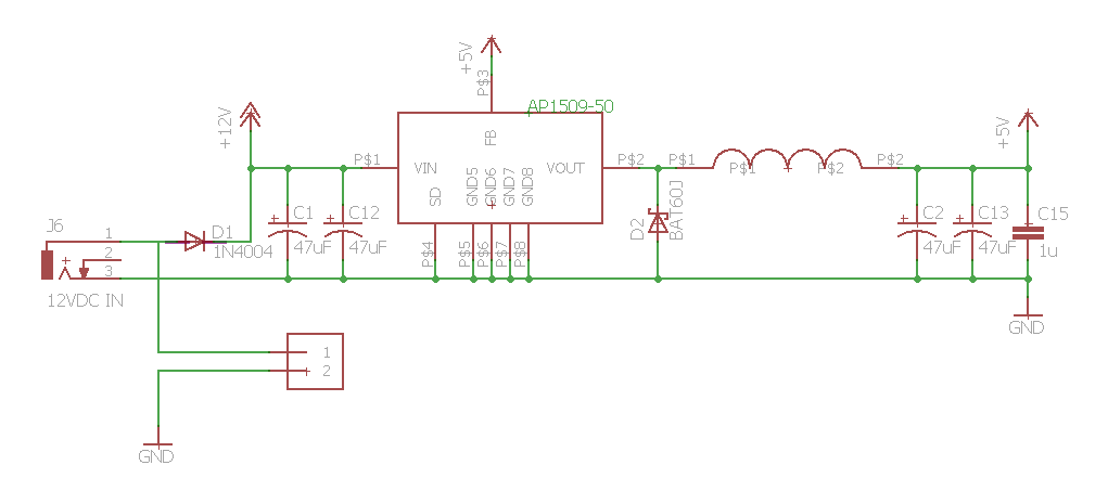
The regulator portion of the schematic is:
[image: Inline image 2]
The regulator portion looks more or less standard, depending on the
value of the capacitors and how the ground currents run.
Not having flyback diodes puts lovely spikes on the lines, so I'd add
these as soon as possible unless your relays have them (best is across
the relays in reverse polarity, of course) or the transistors have
them. However, the transistors having them keeps the transistor
protected... but where does all that energy from the relay coil go?
What is the part number for C2/C13? I would recommend ceramic with a low ESR. Tantalum for Electrolytic will have a higher ESR and will not be suitable as you will see considerable ripple/spikes. Regarding the relays, without the diodes, it will only affect the transistors and not the power supply. You want a diode across the relay to prevent the transistor collector voltage from rising above the relay supply voltage. When the relay switches off, the reverse EMF will cause the voltage on the transistor to exceed the relay supply voltage and potentially damage the transistor. With the diode, the energy from the reverse EMF will be dumped into the relay supply. If you have low EMF ceramic capacitors across the relay supply, the supply will remain clean.
I probed the 5V line of my setup today, with and without a BBB attached to my cape.
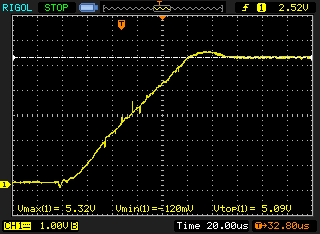
With no BBB attached, the unloaded startup looks like this:
There’s considerable noise here, but it doesn’t seem to exceed the limits of the TPS65217.
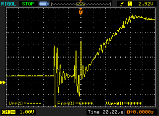
When the BBB is connected to the cape, startup looks like this:
So I don’t think the issue is with startup transients.
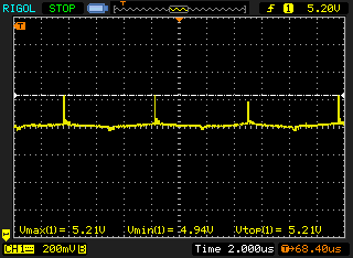
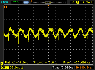
During normal operation, the 5V rails looks like this:
There are 200mV spikes at 150kHz due to the switcher. I haven’t seen those spikes much larger than 200mV, but if they were then I could see them damaging the TPS65217.
The capacitors I’ve been using on my power supply are electrolytic. I can add some ceramic capacitors as well.
Does this all make sense? Any other ideas for what may have happened to my BBBs?
When measuring with an oscilloscope, keep the probe as short as possible. For example, short the ground to the probe tip and place the probe near the switcher. If you still see the switching spikes, then your probe ia too long. A ground wire of 3 or 4 inches is too long. As I said before, electrolytic capacitors are no good for switchers because their ESR is way too high. Ceramic capacitors with a low ESR will clean up your power supply noise and make a big difference. Even tantalum capacitors are no good for switchers generally speaking. If you look at most vendor reference designs, they always use ceramic capacitors. In fact, some switchers won’t work unless you use ceramic capacitors.
I hear you on the ceramic capacitors. I’ll be switching those out tomorrow. For now I wanted to get an idea of what the power rail looked like with the current setup, so I could see if there was anything else that may obviously be contributing to the burned out BBBs that I have.
I’m not sure I understand what you’re saying about the probe though. Are you suggesting to shorten the ground wire coming off the oscope probe itself? When you say to short the ground to the probe tip and place it near the switcher, is this to use the ground wire of the probe as an antenna?
What I’m recommending is to avoid any antenna pickup by the probe. If you are using a regular probe, then you should probably use something like this:
Scroll down to about half way "Tektronix P6106 probe with sleeve removed and grounding clip in place.”
That is what I mean by keeping the ground line short. To diagnose your problem, you must start with measurements that you can trust. What is the bandwidth of your scope?
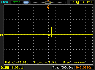
Thanks John. You were definitely right about my probe ground wire being too long. I shortened them up as shown in the page you linked to, and the those spikes I was seeing at 150kHz disappeared.
The 5V signal now looks like this:
That’s definitely not enough noise to cause any problems on the BBB.
There is a bit of noise immediately upon plugging the wall wart into the wall:
But the voltage rise after that looks fine to me:
One thing to note is that these BBBs died after a few days of operation, not when they were plugged in.
It may have been due to the electrolytic caps, which I’ve now replaced. It sounds like it probably wasn’t the relays switching. Is there anything else I should check?
Scope traces look good, so nothing I can see will affect your BBBs. Another thing that can affecting your BBB will be large ground currents flowing through the BBB. Best advise is to create a ground reference point and then connect all grounds in a star pattern from that reference point. Don’t supply power into one end of the BBB and then supply power to another device from the other end of the BBB. Best reference point will be close to the BBB power connector or P9Pin1&2. Don’t connect any of the other ground pins to your circuits.
How close are the relays to the BBB? I was thinking that perhaps there is some inductive loop between the relay coil and some circuit on the BBB. I would be very surprised because the BBB PCB layout is designed to have very low EMC susceptibility, but it could be that your PCB isn’t designed all that well and is feeding back this induced voltage back into the BBB via one of the power supply rails. Which supply rails are you using? Can you monitor those rails with your scope to see what happens when you operate those relays? Again, keep the scope probe ground wire short. The BBB regulator does have some protection, but if it gets hit over and over again, it will fail eventually.