[PRU] Reading from DDR RAM

I have tried to adapt an example where the host program writes a value to the ddr memory and the pru reads these values and outputs the values to a gpio pin.
but somehow i did not manage to read the correct data from the memory. i am new to this topic (especially memory management), so this might be a simple question, but i somehow don’t get this right.

using prussdrv_get_phys_addr in the host program gives me a physical address of 0x9f700000 (it somehow always gives me this value ?), which i send to the pru with an array created by prussdrv_map_prumem.

is this the correct adress to read data from in the pru or do i have to use a different one? I think i have missunderstood something, so if anyone knows the solution or a good source for learning to use these kind of things, i would appreciate any help.
also if someone knows a way to display a register’s value (without ccs), please let me know.

I’d recommend to use PRU shared memory for communication between PRU and main core. From main cores point of view base address of this memory is 0x4a310000, from PRUs point of view it is 0x00010000

In cases where the data being accessed by the PRU, but supplied by Linux is larger than what can fit in PRU shared memory (12kB), what are the mechanics involved with gaining access to the pointers necessary to perform this feat?

From Linux’ perspective, it will be allocating from MMU-protected memory that will need to be declared as shared. So when Linux applications work with this location, it’ll be a virtual address, not a physical address. However when the PRU tries to access main memory, it will go through the OCP_HPx (BBB). However I suspect that when the PRU requests access to global memory, it is going to need to know that physical address or at the very least some ID that will correlate to the target shared memory. This means that the Linux application is going to need to use its pointer to that memory and call virt_to_phys() and then share that value with the PRU so that the PRU can access the shared memory. Normal inter-processor communications (i.e. using the mailbox0) should suffice to make this transfer.

Once the PRU has the physical address, I don’t know if there’s anything special it needs to do with it or if it can use it directly. I’m not sure if the MMU is also in play when a PRU tries to access main memory. If it is, then there will need to be a PRU-equivalent of phys_to_virt() that can take the physical address value and convert it to a virtual address the PRU can use.

Now granted, the OP in this case asked this back in 2016. So I doubt they really care about the answer today. But I do. So instead of creating a new thread, I thought I’d continue the questioning here.

Since I’m working with a BBAI64, the details are slightly different, although I was hoping the concept is similar. Instead of the OCP_HPx, the BBAI64’s TVA4VM requires the PRUs to make use of the CBASS0.
Also note, this is how I assumed it would work, not how it actually can be done. I say this because there’s wording for the J721E TRM that makes me think maybe there’s some formality at play at least for the BBAI64. On that platform, all CBA connections are made up of master and slave components where the master initiates a transfer and a slave is notified of the transfer allowing them to respond to it via Interrupt. That suggests this interconnect through the CBASS0 may not be as peer-to-peer as I was imagining/hoping.

I could also imagine that since the BBB’s AM335x has a 32-bit Cortex A8, that it can share physical addresses with its PRUs in 32-bit form, but the BBAI64 may require a translation layer (RAT???) since the TVA4VM houses a 64-bit Cortex A72 capable of 64-bit memory pointers. This would pose a problem for the other 32-bit based processors in the same microcontroller (i.e. the PRUs, Cortex R5s, etc). So I’m thinking there has to be a 64-bit physical address to 32-bit virtual address translation going on which might explain the presence of Region Address Translation (RAT) which I don’t think existed in the AM335x.

If someone could fill in the gaps, that’d be really useful.

Don’t have any detailed input here, but yes, that’s the role of RAT – mapping 32-bit address space to the host’s. See sections 2.5 and 8.4 of the TDA4VM TRM:

I haven’t looked into it in more detail and would be interested to know what you learn re: the RAT configuration, and especially the default mappings.

I didn’t understand RAT when I read it initially, and even in the context of this conversation, I still don’t think reading over what’s documented really helps me any. Without more description about what RAT is doing, how it is used, or example code showing it being used, I have just as many questions now as I did before.

But just on the surface, it seems RAT is a sub-processor’s way of communicating to the MMU that it needs to declare a memory range for use so the MMU knows to expect/allow those accesses vs blocking them as illegal references.

What’s even more confusing is the NOTE that is right below the passage shown above that reads as follows:

The region base address and translated base address must be aligned to the defined region size. For
example, if the defined region size is 64KB, then the two addresses must be 64KB aligned. This is
software responsibility as RAT does not perform such alignment check. Regions that are not aligned
have unpredictable results.
Moreover, multiple region definitions must not overlap in their covered address space. RAT does not
check for this, so it is software responsibility to take care of it. Overlapping regions may lead to
unpredictable results.

To me, alignment means the address being requested must be an even-multiple of the size. I don’t think Linux or the A72 is held to that requirement and thus any memory it allocates is not going to be aligned based on the size of memory allocated.

This has me thinking that first the available memory declared to Linux is going to have to be altered. There’s BIOS entries that indicate memory ranges that are reserved/not available because they are configuration registers or memory-mapped peripherals. However you can manually add custom ranges to tell Linux to not include those ranges as part of its available heap. Examples on the Internet suggest when taking relatively large chunks of RAM (e.g. 512MB), to pull it from the end as opposed to bumping the starting point. I didn’t get a sense as to the reason other than it was the least likely to be already taken at this point in system startup.

Once Linux has been told not to utilize the range, it can manually be allocated/accessed via mmap. If the PRU is programmatically coordinated to use the same range, then maybe this is a technique that would work? In my case, I only need ~1MB, not 1/2 a Gig. But given this info, I don’t know that the size being allocated really changes the procedure.

I was just hoping someone had already done something like this or had an example of shared DDR between Linux an a PRU already documented somewhere that could be used as a guide in case I actually need to do something like this as part of what I’m working on.

My biggest concern is the DDR Access latency. My thought was to reserve some memory range. Then when Linux is booted, populate it with the content of a BIN file from eMMC. The PRU would be hard-coded with the pointer to the beginning of this RAM-resident BIN file.

At runtime, the PRU would receive a 4-banked 16-bit byte/word request (effectively an 18-bit memory pointer), perform the pointer-math to identify where in the reserved memory that value resides, fetch it from DDR, and do what I need to do with it before hard real time deadlines over-run. But my biggest concern is that access to DDR is just not going to be fast enough or consistent enough to rely on for random 1 and 2-byte accesses. To make matters worse, I can’t really do caching since access to that memory can bounce all around within a 256kB range. I need to review my notes, but the turn-around time, it seems, has to be in the 160ns range. Current solutions doing this use CPLDs and dedicated flash/sram can hit those marks in well under 80ns.

If access to DDR takes, say 40 cycles of a 200MHz PRU, then that puts me right at 160ns. That’s cutting it awfully close! Even if the BBAI64 can run its PRUs at 333MHz, that’s still 120ns and not much room for jitter.

So I’m HOPING I don’t have to rely on this shared DDR memory technique, but I’d at least like to test it just to see how feasible it is. But to do that, I need to understand the mechanics of how it can be attempted. And it’s just interesting to me…

The RAT stuff seems pretty clear to me.

It converts an address in the 32bit space into the 48bit space.

The alignment in 32bit space and 48bit space must both be aligned on the mapping size.

If you map a 4k region, then both the 32bit src address and 48bit dest address must be 4k aligned. If you want to map a 64k area, then both 32&48 bit addresses must be 64k aligned.

This is because the bottom x bits of the address are used to access the memory with the top 48-x bits coming from RAT.

If you access a 32bit address that is not mapped via RAT, then the access will be local to the core, in its 32bit address space.

For some reason, I was mis-interpreting it. And so I re-read the passage, and looked elsewhere in the documentation to see if I could make more sense of it in hopes of making an intelligible response.

And I found where it is further confirmed the purpose of RAT:

And I think the problem is my assumed-meaning of:

  • region
  • base address
  • translated address

In 8.4.1.2, it says RAT has 16 regions. For some reason I had it in my head the regions were each of the 16 subsystems listed in Table 8-46. Now I’m thinking it’s just a coincidence that there are 16 subsystems.

So is a region just a virtual-to-physical address (and range) entry?

Conceptually, it requires a physical address (presumably 48-bit on this platform) and a size (32-bit based on the 2nd sentence after the bullets) to define the range. Then a 32-bit virtual address that the code will use to access this region with needs to be defined. This is the value I was expecting to be referred to as the translated address. But that doesn’t mesh with the wording in the 3rd bullet.

Here are my questions:
Is the base address the virtual (32-bit) address?
What is “the register” that is being referred to in its bullet entry in 8.4.1.2?

Based on the 3rd bullet’s declaration that the Translated Address being 48-bit, is this is the physical address?
And does code set it directly? The rest of the description is confusing to me. But I suspect what it is trying to communicate is that there’s a 64-bit register somewhere and the verbiage is telling me which bits of the 64 are the 48 used.
Again, what is “the register”?

And this seems significant to the relationship between the two addresses:
…the bottom x bits of the address are used to access the memory with the top 48-x bits coming from RAT.
I’m not sure I get exactly what this means. Perhaps if you made an example with real numbers it might jump out at me exactly what this means. But I think my lack of understanding of this statement here is a huge part of why I’m just not getting it yet.

And finally, are the 16 regions in the RAT shared with all of the sub-processors listed in Table 8-46 or does each sub-processor have its own set of 16-regions to define for itself?

Ok, I have been reading through this again and there are certainly things that are not clear.

However as far as the mapping goes.

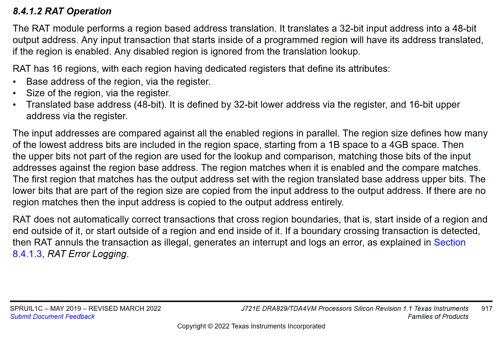
A region is a mapping from 32 bit to 48 bit space. So you can map up to 16 regions.

What is unclear here for me yet, is does each module that needs RAT have its own 16 region RAT module, or is the RAT module global to all cores that need RAT and the 16 regions are shared.

I am inclined to think that there is a RAT module for each core that needs RAT.

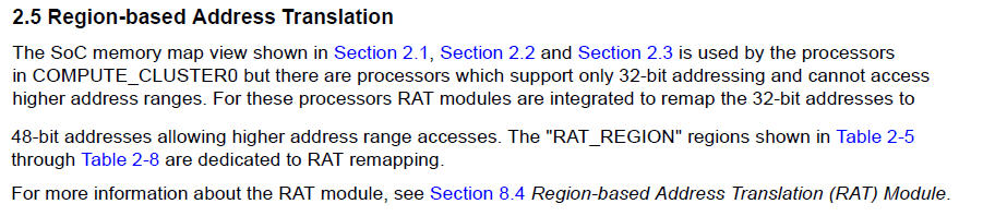
But it is confusing. If you look at the Processors View Memory Map section 2.5
it appears that the 32 bit address space is divided between the various cores.
But I think this is misleading. Taking the Main R5 cores for example. Each has its own ATCM and BTCM memory. That is 4 individual 32k memory banks. However table 2.5 only lists 1 ATCM and 1 BTCM. So at least in the case of the R5 cores, the 32 bit address must be local to the core. I therefore assume that each cores 32 bit address space is only local to that core. If that is the case then each core must have its own RAT module.

That makes the 16 region limit more acceptable.

For mapping, if you look at the J721E_registers3.pdf section 8 you will find the RAT register definitions.

There are 4 main registers ( x 16 regions) that control the mapping.
These are all 32 bit regisiters. The ‘_k’ refers to the region, so these registers are repeated 16 times,

RAT_CTRL_k : has an enable bit and 6 bits to represent the size to use for mapping. Where number of bits is 0 - 32. A value of 0 maps a single 32 bit address to a single 48 bit address. Otherwise the number of bits dictates the size of the region from 2 bytes upto 4G, not that you could use that full space.

RAT_BASE_k: This is the start of the 32 bit address you want to map into 48 bits. The bottom x bits here are 0, where x is the number of bits you specify in RAT_CTRL_k

RAT_TRANS_L_k: This is the bottom 32 bits of the 48 bit address you want to map to. As with RAT_BASE_k the bottom x bits must be 0

RAT_TRANS_U_k: The top 16 bits of the 48 bit address.

Now looking at the Processors View Memory Map you will see that the cores have RAT regions allocated in their address space. These spaces are where you will need to map the 48 bit space into.

If we take an Main R5 core for example. Its address map has 5 RAT regions of various sizes, with ARMSS_RAT_REGION4 being the largest at 2G from 0x80000000 to the top of the 32bit address space.
This is plenty of space and you could map all 16 regions into this space.

So if we take the GPIO registers, they are between 0x0000600000 and 0x00006310FF in 48 bit space.

To map this into the R5 address space you would need to use a RAT size of at least 13 bits 0x1 - 0x1FFF. This would extend beyond the GPIO registers so you would need to make sure you don’t access the undefined region.

So the RAT registers would need to be:

RAT_CTRL_k 0x8000000D - MSB is enable, bottom 6 bits the size.
RAT_BASE_k: 0x80000000
RAT_TRANS_L_k: 0x06000000
RAT_TRANS_U_k: 0x00000000

So with this mapping, if the R5 core reads from 0x80000000 it is actually reading 0x0000600000.

You could map it somewhere else if you wish. For example 0x80002000 is valid (bottom 13 bits are 0) but 0x80000100 is not valid as it is not aligned to 8K

Do that make it any clearer ? This is my understanding of the RAT module.
I could be wrong here of course. It is a very complicated chip.

Not sure if you saw this post yet:

@benedict.hewson That’s what I was looking for. If I’d found those entries in J721E_register3.pdf, it would’ve become much clearer. I have those files, but only skimmed through them. This is the 1st time I’ve actually found something useful in them…and this was very relevant and useful. I just wish that the other places where RAT is documented would make reference to this PDF for more details. But now that it is all laid out, it all makes perfect sense. I see how all the pieces interact, where they go, and how they relate to each other as it relates to creating a RAT region entry. Thanks for following up with this.

@FredEckert I had not found this thread yet. Thanks for pointing it out as it sounds like you were doing exactly what I was envisioning I’d need to do. The mechanics are different. In my case, I’ll allocate a 1MB block and logically break this into multiple 64kB, 128kB, 256kB sections, each section representing a different user-supplied engine tune. But once those sections have been written, they’ll, for the most part, remain as-is. It’ll just be the PRU reading from 1 of those tunes to grab bytes as it needs them. If the user wants to change which tune is the active tune, the ARM will tell the PRU to update its pointer to reference the new active section.

I like the idea of simplifying this down to just 2 sections and flip-flopping between them. So one is the active section for the PRU and the other the active section where the ARM can make edits without collisions with the PRU trying to access data the ARM is changing. Some data-edits need to be atomic, and thus making edits in-place where both PRU and ARM are using the same region could be quite problematic in unpredictable ways. But with this flip-flop technique, when the edits are complete, trigger the flip-flop and the two positions swap making the edits atomic, from the PRU’s perspective.

Regardless of which management mechanism is used, the PRU will need to be in control of when the transition actually occurs so it only performs the transition procedure at “safe points” during execution. For example when the PRU is effectively being told to return a word of data, it would be undesirable for the PRU to fetch the lower byte from one tune and the upper byte from a different tune particularly if that word just happened to be what was different between the two tunes.

Now one of the techniques I found elsewhere on the Internet that people were also using was DMA (Data Movement Arch) to perform the actual transfers between ARM and PRU. But I’m not seeing how this would help my scenario. I could see this possibly being useful if the data I was fetching was a contiguous block of data to essentially be streamed from the ARM to the PRU. But being my fetches will be byte/word sized and quite random in location, I’m not sure that’s the right hammer for my nail.

No surprise, I have a questions…

I found a document that details the PRU Read Latencies that you can expect.:
PRU Read Latencies (Rev. A)

Specifically what I was looking at are the charts that show the read latency of moving data from DDR to Shared memory. As I look through each of the uCs in the document, the values are all over the place.

However the document doesn’t cover J721E/TDA4VM. The closest uC it covers is AM65x, but I don’t see where they list the latency of reading DDR to PRU RAM. Anybody know where that would be documented for the J721E?

Also all the references refer to the number of PRU clock cycles, but many clarify at what frequency the PRU is at. This leads me to suspect that if the PRU is running faster (i.e. 250MHz), that the PRU cycles will be higher. Since the latency has more to do with components outside the PRU, I doubt the speed of the PRU is going to reduce the latency. But I would like an idea of what the latency is and some confirmation on what the PRU max clock speed is in J721E. The only place I could find speeds of PRU_ICSSG’s documented is in a TI PRU_ICSSG Getting Started guide, sec 1.4.2.

The latency document also makes reference to L3/L4 interconnects (sec 3.2) that the PRU fetch will have to go through. Normally when I see “L” followed by a number, I think cache layers, like L1, or L2 cache. I suspect they are using the L to generically refer to architectural layers. But given the nature of how DDR memory bursts data in parallel, not individual bytes like a traditional SRAM, it would make sense that there would be a cache. If there is a cache, does this mean subsequent reads to data just past where a previous read occurred will have latency improvements? I’d think if that existed, it would be discussed in a document talking about latencies. But the latency document doesn’t contain the word “cache” anywhere. So does anybody know whether there is a DDR cache for PRUs?

So for instance, lets say I have my reserved DDR memory configured in a RAT region to appear at 0x2000_0000 (32-bit virtual). However the 4 bytes I actually need are at offset 0x1F (notice its an odd address).

To make this a single transfer from DDR, I need to write the C-code so that it makes used of the Load Byte Burst (LBBO or LBCO) instruction. The examples for those instructions show using memcpy(). So lets do that:

unsigned char* ddr = 0x20000000; // 32-bit virtual RAT address to DDR
unsigned char[4] bytes; // Will compiler allocate this in a Register??? 
unsigned int offset = 0x1Fh;
memcpy(bytes, (ddr + offset), 4); // I'm assuming compiler will do the pointer math without a cast?

Also if the 4 bytes I’m needing from DDR just happen to be across DDR-pages, I could see this being 2 DDR fetches to get all 4 bytes despite the use of the the more efficient LBBO/LBCO. I’m hoping that detail would be handled at the DDRSS level and thus wouldn’t be a significant addition to the latency (i.e. it won’t double the latency).

I’m just trying to determine what the most efficient way of fetching random-location data from DDR is, at the programming level…preferably using C.