The PRU Cookbook has two examples for using PRU UART: PRU Cookbook
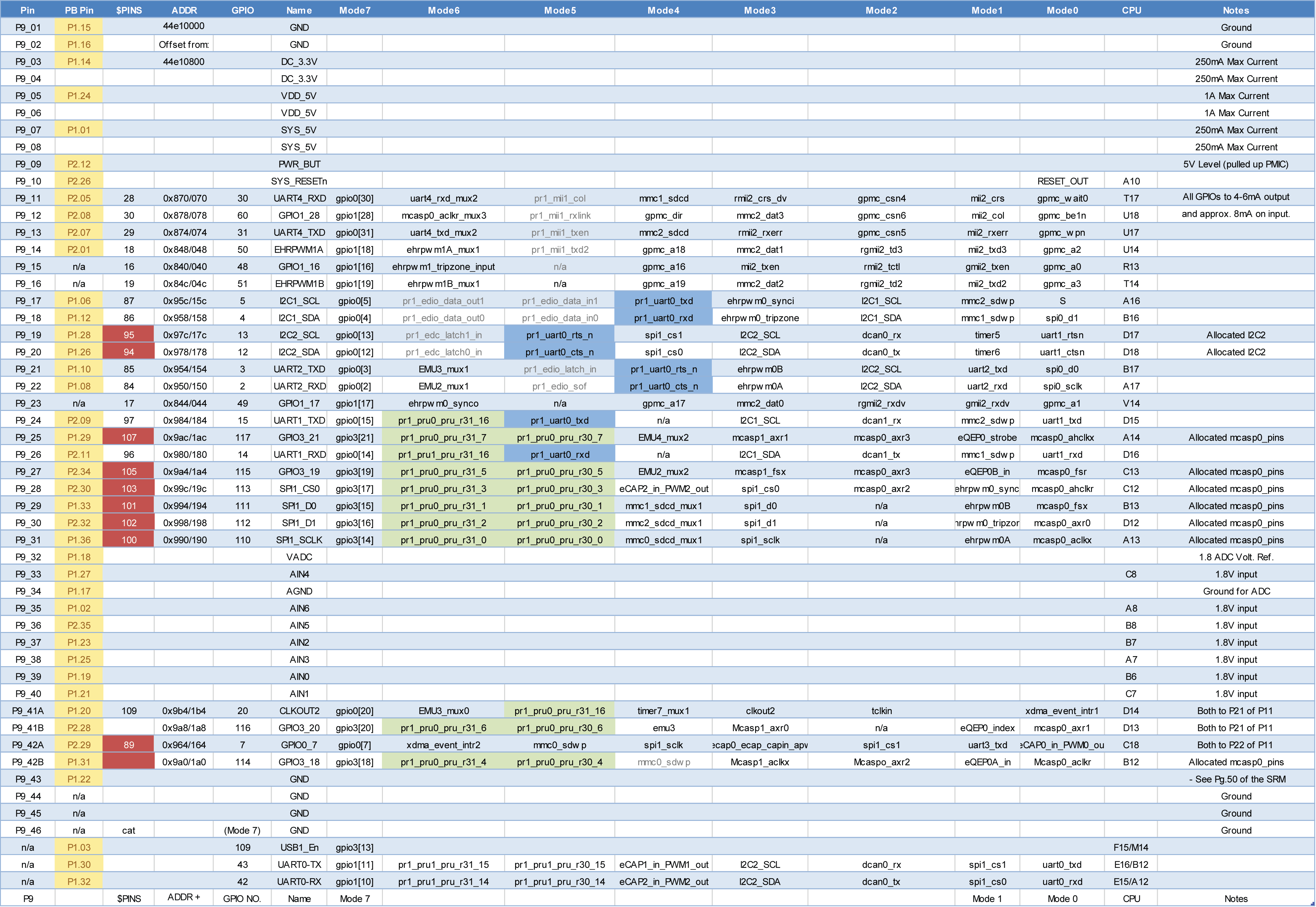
It seems they are using Serial Debug Header for PRU UART i/o (there’s a picture showing this header where the FTDI cable should be attached). But they configure P9_24 and P9_26 pins to pru_uart mode.
I built and uploaded the firmware to the PRU and ran it. When I connected my FTDI cable to the Serial Debug Header, I saw only Linux console login prompt.
I couldn’t readily connect my FTDI cable to P9 header as they are both female.
Is there any way to get PRU UART i/o on the Serial Debug Header of the BBB, or is it just the mistake in the PRU Cookbook?
Just be aware that P9-24, P9-26 are also DCAN1 and the only CAN port available if you are using cape EEROMs which use I2C instead of DCAN0. One of the LCD capes I bought that that problem. They could have used a different I/O for the buttons but instead used one of the CAN pins which made it useless for a remote CANopen display and control panel.
