Hi John,
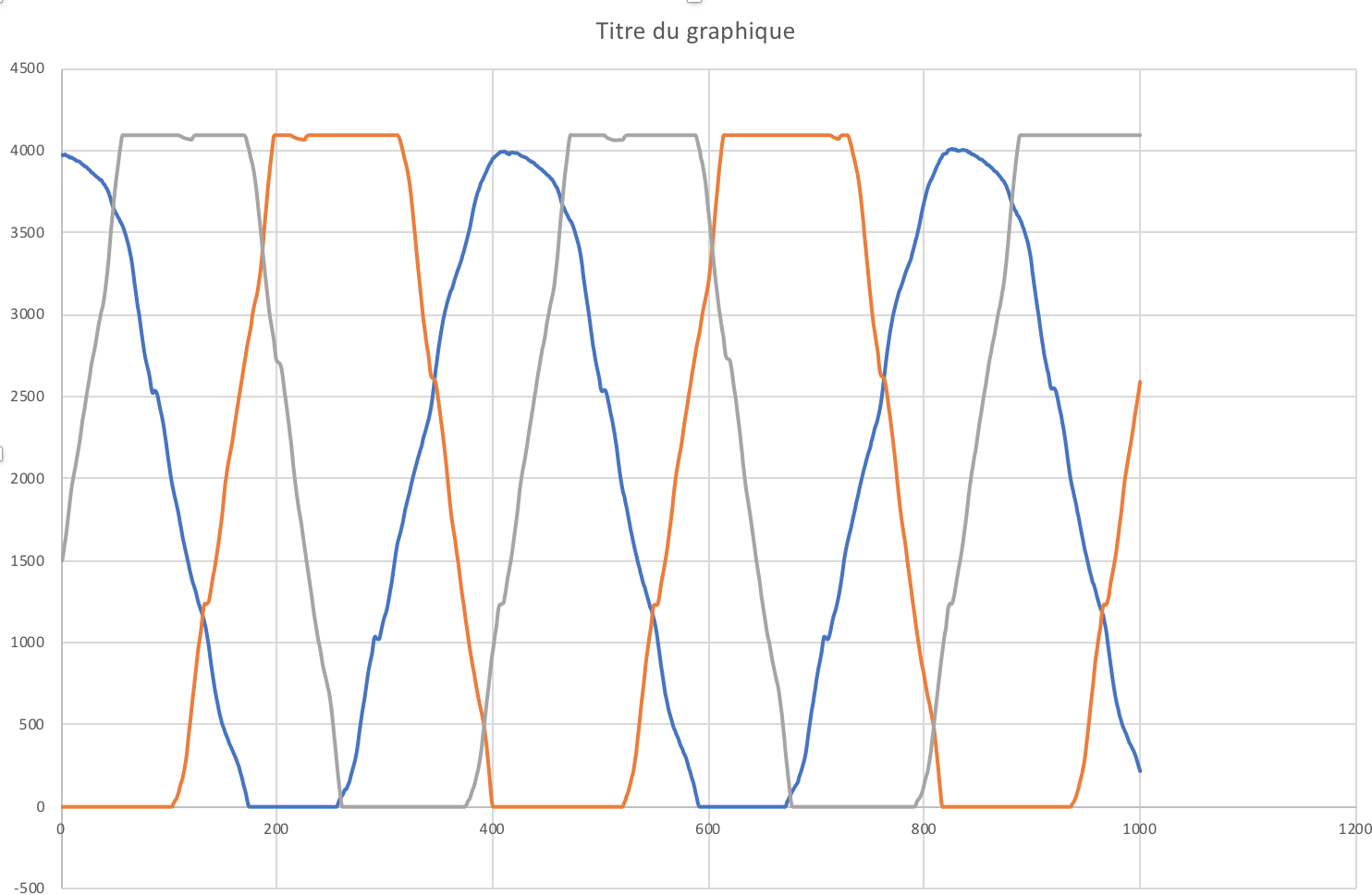
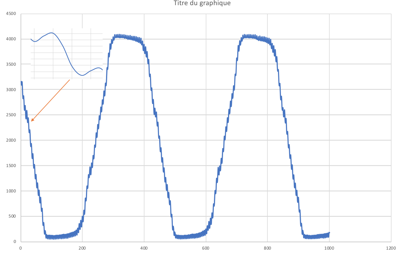
Thanks for the help, I looked into the iio_generic_buffer.c example and i patched it to disable the hardware triggers thanks to the patch presented on this page : https://www.teachmemicro.com/beaglebone-black-adc/ I am now able to reader a buffer from the different channel.
However I have 2 majors questions that remains:
-
I only want to use on channel, then I do not want the ADC to sample the other one so that i’ll have the maximum sampling rate. What is the best way to disable the channel? If I do not enable them in iio_generic_buffer.c I am not sure that the ADC is not going to sample this channel or not (well, I think it wont sample but I prefer to be sure). Is it preferable to not mention them on the devicetree so that Linux wont know that there are multiple channels on the ADC? This part is not very clear for me.
-
To change the sample frequency of the ADC you mentioned that it is done using the device tree however I did not find any argument on the ADC devicetree to change the sampling frequency. I read the discussion you had on this post (https://patchwork.kernel.org/patch/9391487/ ) but it is not clear if the frequency setting is done using the kernel module or devicetrees. Could you explain me this please?
Looking at this a little more, there is a mistake in the ADC DT file BB-ADC-0A00.dts. The maximum averaging is 16, not 0x16.
The line
ti,chan-step-avg = <0x16 0x16 0x16 0x16 0x16 0x16 0x16 0x16>
should be changed to
ti,chan-step-avg = <16 16 16 16 16 16 16 16>
Fortunately, the driver does a range check and sets the value to 16.
ti,chan-step-avg = <1 1 1 1 1 1 1 1> /* 2 sample average */
ti,chan-step-opendelay = <0 0 0 0 0 0 0 0>
ti,chan-step-sampledelay = <0 0 0 0 0 0 0 0>
To achieve a conversion rate of 800 KS/s
From ti_am335x_tscad.c, 1 + (1 + 13) * 2 = 30 cycles
The ADC uses a 24 MHz clock, so 1/24,000,000 * 15 = 800 KS/s
You could increase the sampling rate to 1.6MS/s by changing the average to 0, which means there is no averaging. To achieve this, the minimum number of cycles for a conversion is 15 (12.3.7 of the AM3358 Technical Reference Manual)
1 + (1 + 13) * 1 = 15 cycles
which will give you 1.6 MS/s
Regards,
John