RE: RelayCape and Schematics...

Hello,

I have a RelayCape from GHI and the bbb.io peoples. I think my issue is my issue and I need assistance w/ it.

So…

I connect my 12v LED to the Cape like this:

  • COMMON (COM) to 12v battery (positive)
  • NORMALLY OPEN (NO) or NORMALLY CLOSED (NC) to the LED negative lead
  • Then…I put an additional wire to the negative lead on the LED to the 12v battery (negative)/GND
    So, here lies the issue.

I have tried w/ COM being my positive wire and negative wire but not at the same time or simultaneously.

SetDown.PNG

That is a small fritzing photo to give some insight.

Seth

P.S. Now, the Cape works w/ the source. I can turn it on and off, w/ a timer, w/ source. Some nodejs and bonesrcript does the trick.

SetDown.PNG

So, I’m guessing you got this running now.

However, considering you have the Relay Cape from the BB Cape list, I am not sure if you had seen the link to the brd and Schematic files:
https://github.com/beagleboard/capes/tree/master/beaglebone/Relay

Jon

Hello,

I have the RelayCape from the Cape list on beagleboard.org. I saw the files. I have not gotten the RelayCape working just yet.

I was dealing w/ some individuals on #beagle at Freenode on this subject.

I even tested a LED, 12v outdoor LED, to the RelayCape. I have been unsuccessful so far.

Seth

P.S. I will try a motor soon and reply.

Don’t you need a resistor between the power and the LED? Something like a 330 Ohm to 1K Ohm? Or is this like an automotive Lamp that you are using?

Are you hearing the relay trigger at all with the code you are using?
Can you share this?

Jon

Hello,

I hear the click of the Relay1, Relay2, and Relay3. All of the LEDs signifying the on of the I/O on those three relays turn on and off.

The automotive LED is not what I am using any longer. I am going to try to use a motor for just turning it off and on.

Seth

P.S. The source I am using is a simple bonescript code for a LED but I am going to use it to turn on GPIO_112 or P9.30 now w/ the motor. I will reply once this is completed.

Hello Sir,

Seth here. I tried w/ the motor. It seems I cannot use config-pin on my current image for some reason. So, even though the Cape seems to work, I am not receiving any I/O on my pin b/c of not being able to control the pins.

Seth

P.S. I will reflash a new image and reply back.

Hello,

Here is my issue:

`

P9_30 pinmux file not found!
Cannot read pinmux file: /sys/devices/platform/ocp/ocp*P9_30_pinmux/state

`

It seems I cannot mux my pins.

Seth

P.S. I got a new image from bbb.io/latest-images, too. The IoT image.

Hello,

I have a RelayCape from GHI and the bbb.io peoples. I think my issue is my
issue and I need assistance w/ it.

  A link to the source would help... Google shows lots of "relay
capes"... I'm going to assume it is the 4-relay unit shown on
https://beagleboard.org/capes

So...

I connect my 12v LED to the Cape like this:

  A link to the LED would be useful too... I'm going to presume you mean
something like
Amazon.com which
has an internal limiting resistor sized for a 12V supply.

  - COMMON (COM) to 12v battery (positive)

  <ouch>

  Most circuits treat "COM" as GND level. Hopefully these relays are
fully isolated (a non-isolated relay would have the ground level shared
between the switched output and the low-side control input -- and if you
connected one of those with a high "com", you are putting 12V onto the BBB
ground side -- and maybe on the GPIOs which burn out at more than 3.3V)

{You may be safe -- presuming I'm looking at the correct schematic, the
relays are isolated -- but FYI: the COM connection is described as
"RELAY#.COM.GND"
I'm also assuming the cape incorporates protection against back EMF going
into the BBB GPIO -- at the least, via a transistor switch maybe with
diodes; this protection will not be seen in diagrams using discrete relays}

  - NORMALLY OPEN (NO) or NORMALLY CLOSED (NC) to the LED negative lead
  - Then...I put an additional wire to the negative lead on the LED to the
  12v battery (negative)/GND

  That makes no sense...

  Try:

Battery + to LED + lead,
LED - lead to relay NC,
Relay COM to battery -

  The LED should glow (you don't need to have a BBB connected for this --
since the NC should make a complete circuit on the high voltage side). If
the LED doesn't glow, try swapping the leads on it. There is no sense in
worrying about the BBB until you get the LED on the NC connection to glow
all by itself. Only then can you worry about a program to make the BBB
toggle the relay state.

pseudo-relay_schem.png

Hello,

Here is my issue:

P9_30 pinmux file not found!
Cannot read pinmux file: /sys/devices/platform/ocp/ocp*P9_30_pinmux/state

  Please include the command which produced these error messages...

It seems I cannot mux my pins.

  An up-to-date* IoT image with no capes shows:

debian@beaglebone:~$ ls /sys/devices/platform/ocp/
40300000.ocmcram 481d0000.can ocp:P8_15_pinmux
ocp:P9_14_pinmux
44e07000.gpio 481d8000.mmc ocp:P8_16_pinmux
ocp:P9_15_pinmux
44e09000.serial 48300000.epwmss ocp:P8_17_pinmux
ocp:P9_16_pinmux
44e0b000.i2c 48302000.epwmss ocp:P8_18_pinmux
ocp:P9_17_pinmux
44e0d000.tscadc 48304000.epwmss ocp:P8_19_pinmux
ocp:P9_18_pinmux
44e35000.wdt 48310000.rng ocp:P8_26_pinmux
ocp:P9_19_pinmux
44e3e000.rtc 49000000.edma ocp:P8_27_pinmux
ocp:P9_20_pinmux
47400000.usb 49800000.tptc ocp:P8_28_pinmux
ocp:P9_21_pinmux
48022000.serial 49900000.tptc ocp:P8_29_pinmux
ocp:P9_22_pinmux
48024000.serial 49a00000.tptc ocp:P8_30_pinmux
ocp:P9_23_pinmux
4802a000.i2c 4a100000.ethernet ocp:P8_31_pinmux
ocp:P9_24_pinmux
48030000.spi 4a326004.pruss-soc-bus ocp:P8_32_pinmux
ocp:P9_25_pinmux
48042000.timer 4c000000.emif ocp:P8_33_pinmux
ocp:P9_26_pinmux
48044000.timer 53100000.sham ocp:P8_34_pinmux
ocp:P9_27_pinmux
48046000.timer 53500000.aes ocp:P8_35_pinmux
ocp:P9_28_pinmux
48048000.timer 56000000.sgx ocp:P8_36_pinmux
ocp:P9_29_pinmux
4804a000.timer driver_override ocp:P8_37_pinmux
ocp:P9_30_pinmux
4804c000.gpio modalias ocp:P8_38_pinmux
ocp:P9_31_pinmux
48060000.mmc ocp:A15_pinmux ocp:P8_39_pinmux
ocp:P9_41_pinmux
480c8000.mailbox ocp:cape-universal ocp:P8_40_pinmux
ocp:P9_42_pinmux
480ca000.spinlock ocp:l4_wkup@44c00000 ocp:P8_41_pinmux
ocp:P9_91_pinmux
4819c000.i2c ocp:P8_07_pinmux ocp:P8_42_pinmux
ocp:P9_92_pinmux
481a0000.spi ocp:P8_08_pinmux ocp:P8_43_pinmux of_node
481a6000.serial ocp:P8_09_pinmux ocp:P8_44_pinmux power
481a8000.serial ocp:P8_10_pinmux ocp:P8_45_pinmux subsystem
481aa000.serial ocp:P8_11_pinmux ocp:P8_46_pinmux uevent
481ac000.gpio ocp:P8_12_pinmux ocp:P9_11_pinmux
481ae000.gpio ocp:P8_13_pinmux ocp:P9_12_pinmux
481cc000.can ocp:P8_14_pinmux ocp:P9_13_pinmux
debian@beaglebone:~$

debian@beaglebone:~$ config-pin -i P9_30
Pin name: P9_30
Function if no cape loaded: gpio
Function if cape loaded: default gpio gpio_pu gpio_pd gpio_input spi pwm
pruout pruin
Function information: gpio3_16 default gpio3_16 gpio3_16 gpio3_16 gpio3_16
spi1_d1 ehrpwm0_tripzone_input pru0_out2 pru0_in2
Kernel GPIO id: 112
PRU GPIO id: 144
debian@beaglebone:~$

debian@beaglebone:~$ config-pin -q P9_30
P9_30 Mode: default Direction: in Value: 0
debian@beaglebone:~$
debian@beaglebone:~$ config-pin P9_30 out
debian@beaglebone:~$ config-pin -q P9_30
P9_30 Mode: gpio Direction: out Value: 0
debian@beaglebone:~$

debian@beaglebone:~$ sudo /opt/scripts/device/bone/show-pins.pl
[sudo] password for debian:
P8.25 / eMMC d0 0 U7 fast rx up 1 mmc 1 d0
mmc@481d8000 (pinmux_emmc_pins)
P8.24 / eMMC d1 1 V7 fast rx up 1 mmc 1 d1
mmc@481d8000 (pinmux_emmc_pins)
P8.05 / eMMC d2 2 R8 fast rx up 1 mmc 1 d2
mmc@481d8000 (pinmux_emmc_pins)
P8.06 / eMMC d3 3 T8 fast rx up 1 mmc 1 d3
mmc@481d8000 (pinmux_emmc_pins)
P8.23 / eMMC d4 4 U8 fast rx up 1 mmc 1 d4
mmc@481d8000 (pinmux_emmc_pins)
P8.22 / eMMC d5 5 V8 fast rx up 1 mmc 1 d5
mmc@481d8000 (pinmux_emmc_pins)
P8.03 / eMMC d6 6 R9 fast rx up 1 mmc 1 d6
mmc@481d8000 (pinmux_emmc_pins)
P8.04 / eMMC d7 7 T9 fast rx up 1 mmc 1 d7
mmc@481d8000 (pinmux_emmc_pins)
P8.19 8 U10 fast rx down 7 gpio 0.22
ocp/P8_19_pinmux (pinmux_P8_19_default_pin)
P8.13 9 T10 fast rx down 7 gpio 0.23
ocp/P8_13_pinmux (pinmux_P8_13_default_pin)
P8.14 10 T11 fast rx down 7 gpio 0.26
ocp/P8_14_pinmux (pinmux_P8_14_default_pin)
P8.17 11 U12 fast rx down 7 gpio 0.27
ocp/P8_17_pinmux (pinmux_P8_17_default_pin)
P8.12 12 T12 fast rx down 7 gpio 1.12
ocp/P8_12_pinmux (pinmux_P8_12_default_pin)
P8.11 13 R12 fast rx down 7 gpio 1.13
ocp/P8_11_pinmux (pinmux_P8_11_default_pin)
P8.16 14 V13 fast rx down 7 gpio 1.14
ocp/P8_16_pinmux (pinmux_P8_16_default_pin)
P8.15 15 U13 fast rx down 7 gpio 1.15
ocp/P8_15_pinmux (pinmux_P8_15_default_pin)
P9.15 16 R13 fast rx down 7 gpio 1.16
ocp/P9_15_pinmux (pinmux_P9_15_default_pin)
P9.23 17 V14 fast rx down 7 gpio 1.17
ocp/P9_23_pinmux (pinmux_P9_23_default_pin)
P9.14 18 U14 fast rx down 7 gpio 1.18
ocp/P9_14_pinmux (pinmux_P9_14_default_pin)
P9.16 19 T14 fast rx down 7 gpio 1.19
ocp/P9_16_pinmux (pinmux_P9_16_default_pin)
P9.11 28 T17 fast rx up 7 gpio 0.30
ocp/P9_11_pinmux (pinmux_P9_11_default_pin)
P9.13 29 U17 fast rx up 7 gpio 0.31
ocp/P9_13_pinmux (pinmux_P9_13_default_pin)
P9.12 30 U18 fast rx up 7 gpio 1.28
ocp/P9_12_pinmux (pinmux_P9_12_default_pin)
P8.26 31 V6 fast rx up 7 gpio 1.29
ocp/P8_26_pinmux (pinmux_P8_26_default_pin)
P8.21 / eMMC clk 32 U9 fast rx up 2 mmc 1 clk
mmc@481d8000 (pinmux_emmc_pins)
P8.20 / eMMC cmd 33 V9 fast rx up 2 mmc 1 cmd
mmc@481d8000 (pinmux_emmc_pins)
P9.15 34 T13 fast rx up 7 gpio 2.00
P8.18 35 V12 fast rx down 7 gpio 2.01
ocp/P8_18_pinmux (pinmux_P8_18_default_pin)
P8.07 36 R7 fast rx up 7 gpio 2.02
ocp/P8_07_pinmux (pinmux_P8_07_default_pin)
P8.08 37 T7 fast rx up 7 gpio 2.03
ocp/P8_08_pinmux (pinmux_P8_08_default_pin)
P8.10 38 U6 fast rx up 7 gpio 2.04
ocp/P8_10_pinmux (pinmux_P8_10_default_pin)
P8.09 39 T6 fast rx up 7 gpio 2.05
ocp/P8_09_pinmux (pinmux_P8_09_default_pin)
P8.45 / hdmi / sysboot 0 40 R1 fast rx down 7 gpio 2.06
ocp/P8_45_pinmux (pinmux_P8_45_default_pin)
P8.46 / hdmi / sysboot 1 41 R2 fast rx down 7 gpio 2.07
ocp/P8_46_pinmux (pinmux_P8_46_default_pin)
P8.43 / hdmi / sysboot 2 42 R3 fast rx down 7 gpio 2.08
ocp/P8_43_pinmux (pinmux_P8_43_default_pin)
P8.44 / hdmi / sysboot 3 43 R4 fast rx down 7 gpio 2.09
ocp/P8_44_pinmux (pinmux_P8_44_default_pin)
P8.41 / hdmi / sysboot 4 44 T1 fast rx down 7 gpio 2.10
ocp/P8_41_pinmux (pinmux_P8_41_default_pin)
P8.42 / hdmi / sysboot 5 45 T2 fast rx down 7 gpio 2.11
ocp/P8_42_pinmux (pinmux_P8_42_default_pin)
P8.39 / hdmi / sysboot 6 46 T3 fast rx down 7 gpio 2.12
ocp/P8_39_pinmux (pinmux_P8_39_default_pin)
P8.40 / hdmi / sysboot 7 47 T4 fast rx down 7 gpio 2.13
ocp/P8_40_pinmux (pinmux_P8_40_default_pin)
P8.37 / hdmi / sysboot 8 48 U1 fast rx down 7 gpio 2.14
ocp/P8_37_pinmux (pinmux_P8_37_default_pin)
P8.38 / hdmi / sysboot 9 49 U2 fast rx down 7 gpio 2.15
ocp/P8_38_pinmux (pinmux_P8_38_default_pin)
P8.36 / hdmi / sysboot 10 50 U3 fast rx down 7 gpio 2.16
ocp/P8_36_pinmux (pinmux_P8_36_default_pin)
P8.34 / hdmi / sysboot 11 51 U4 fast rx down 7 gpio 2.17
ocp/P8_34_pinmux (pinmux_P8_34_default_pin)
P8.35 / hdmi / sysboot 12 52 V2 fast rx down 7 gpio 0.08
ocp/P8_35_pinmux (pinmux_P8_35_default_pin)
P8.33 / hdmi / sysboot 13 53 V3 fast rx down 7 gpio 0.09
ocp/P8_33_pinmux (pinmux_P8_33_default_pin)
P8.31 / hdmi / sysboot 14 54 V4 fast rx down 7 gpio 0.10
ocp/P8_31_pinmux (pinmux_P8_31_default_pin)
P8.32 / hdmi / sysboot 15 55 T5 fast rx down 7 gpio 0.11
ocp/P8_32_pinmux (pinmux_P8_32_default_pin)
P8.27 / hdmi 56 U5 fast rx down 7 gpio 2.22
ocp/P8_27_pinmux (pinmux_P8_27_default_pin)
P8.29 / hdmi 57 R5 fast rx down 7 gpio 2.23
ocp/P8_29_pinmux (pinmux_P8_29_default_pin)
P8.28 / hdmi 58 V5 fast rx down 7 gpio 2.24
ocp/P8_28_pinmux (pinmux_P8_28_default_pin)
P8.30 / hdmi 59 R6 fast rx down 7 gpio 2.25
ocp/P8_30_pinmux (pinmux_P8_30_default_pin)
P9.22 / spi boot clk 84 A17 fast rx up 7 gpio 0.02
ocp/P9_22_pinmux (pinmux_P9_22_default_pin)
P9.21 / spi boot in 85 B17 fast rx up 7 gpio 0.03
ocp/P9_21_pinmux (pinmux_P9_21_default_pin)
P9.18 / spi boot out 86 B16 fast rx up 7 gpio 0.04
ocp/P9_18_pinmux (pinmux_P9_18_default_pin)
P9.17 / spi boot cs 87 A16 fast rx up 7 gpio 0.05
ocp/P9_17_pinmux (pinmux_P9_17_default_pin)
P9.42a 89 C18 fast rx down 7 gpio 0.07
ocp/P9_42_pinmux (pinmux_P9_42_default_pin)
P9.20 / cape i²c sda 94 D18 fast rx up 3 i²c 2 sda
ocp/P9_20_pinmux (pinmux_P9_20_default_pin)
P9.19 / cape i²c scl 95 D17 fast rx up 3 i²c 2 scl
ocp/P9_19_pinmux (pinmux_P9_19_default_pin)
P9.26 96 D16 fast rx up 7 gpio 0.14
ocp/P9_26_pinmux (pinmux_P9_26_default_pin)
P9.24 97 D15 fast rx up 7 gpio 0.15
ocp/P9_24_pinmux (pinmux_P9_24_default_pin)
P9.31 / hdmi audio clk 100 A13 fast rx down 7 gpio 3.14
ocp/P9_31_pinmux (pinmux_P9_31_default_pin)
P9.29 / hdmi audio fs 101 B13 fast rx down 7 gpio 3.15
ocp/P9_29_pinmux (pinmux_P9_29_default_pin)
P9.30 102 D12 fast rx 7 gpio 3.16
ocp/P9_30_pinmux (pinmux_P9_30_gpio_pin)
P9.28 / hdmi audio data 103 C12 fast rx down 7 gpio 3.17
ocp/P9_28_pinmux (pinmux_P9_28_default_pin)
P9.42b 104 B12 fast rx down 7 gpio 3.18
ocp/P9_92_pinmux (pinmux_P9_92_default_pin)
P9.27 105 C13 fast rx down 7 gpio 3.19
ocp/P9_27_pinmux (pinmux_P9_27_default_pin)
P9.41 106 D13 fast rx down 7 gpio 3.20
ocp/P9_91_pinmux (pinmux_P9_91_default_pin)
P9.25 / audio osc 107 A14 fast rx down 7 gpio 3.21
ocp/P9_25_pinmux (pinmux_P9_25_default_pin)
P9.41 / jtag emu3 109 D14 fast rx down 7 gpio 0.20
ocp/P9_41_pinmux (pinmux_P9_41_default_pin)
debian@beaglebone:~$

  If these commands are producing errors for you, then /something/ has
changed your device tree configuration, disabling GPIOs.

* The images at Latest Software Images - BeagleBoard are from August of
last year, if you haven't run
  sudo apt update
  sudo apt upgrade
then you have a very out-of-date image.

o/~ talking to myself in public o/~

Hello Again Sir,

Seth here. Okay, I think I was not able to mux my pins b/c of the Cape being attached. Someone said that these Capes were already to work w/ EEPROM.

This is probably why I could not mux P9.30. P9.30 is Relay3.

I will try again w/ your instruction. I tried so many routes, I may have gotten a bit agitated w/ myself.

I will be reading over your ideas soon. I only missed the captions of photos you put together.

Seth

P.S. It may be easier to test a motor on my side of things but I will figure out how to wire this automotive LED soon. It may take some soldering but I will get to it.

Hello,

Seth here again…

Okay. Here are the links to what I have currently in my possession.

https://github.com/beagleboard/capes/tree/master/beaglebone/Relay

https://shop.advanceautoparts.com/p/sylvania-3157-white-syl-led-mini-bulb-pack-of-2-3157slbp2/11137537-p?product_channel=local&store=8598&adtype=pla&product_channel=local&store_code=8598&gclid=Cj0KCQjwjoH0BRD6ARIsAEWO9Dto3PIICpZ7V7Q_cCqa8kLvBBYKnt9IQFolOQlDKFLqSOQ_VvFkS10aArABEALw_wcB&gclsrc=aw.ds

Sorry for the long link.

Seth

P.S. As you can see on the LED, it is near impossible, w/out soldering, to connect wiring. And yes sir, I am using the RelayCape from GHI.

If the Relays are clicking and the LEDs on the relay board light with the code you are using, then I would suspect that it fine. Perhaps it is your circuit that is in question.

Jon

Hello Jon,

Seth here. That is what I am thinking. I read over multiple tutorials and watched some videos on wiring NO, NC, and COM on a relay.

I stuck my meter in Relay1, Relay2, and Relay3 while running the source. I was not receiving any difference in voltage when the source ran which made my relay click and the onboard LED light up.

Seth

P.S. I think it was my circuit. No doubt but I also have ideas b/c of probing w/ the meter in the screw terminals while running source and all while the onboard LED lit up and the clicking gave way of the relays working. “Still testing!”

Are these normal electro-mecanical relays?
Are the contacts isolated from the coil and cape?

There are also toggle relays, which require a positive coil voltage to set and a negative coil voltage to reset. You are NOT using one of these?

To test the coil side.

The cape drives the coil and you can normally hear the contacts switch when the coil is energized or denergized.

The posts before where trying to test the contact circuit.
Without the relay, does the battery light the lamp/LED?
Without the relay coil energized, does the battery light the lamp/LED through the relay COM (common) and NC?
With the relay coil energized by the cape, does the battery light the lamp/LED through the relay COM and NO?

Just noticed your first post,

Battery + positive to relay common.
relay NC to LED Anode + positive.
LED K cathode - negative to battery - negative.

Hello Mr. Robert,

Seth here. I have been getting a lot of responses thus far. I will attempt some ideas and get back to you too.

Seth

P.S. I need to get my soldering iron back on the bench. I will solder this LED and go w/ what you have described to test it. Thank you for your support.

What type of meter, and what mode was it in?

  The simplest test with a DVM (or, if anyone still has such, a VOM) is
to set it in RESISTANCE mode, or CONTINUITY check mode (Continuity mode
typically has a beeper -- if a circuit is open, no sound, if a circuit is
closed, beeeeeeeeeeeeeep).

  Lock the black lead in the COM socket (it really doesn't matter which
lead you put in COM, since all the voltage used comes from the meter
itself, but better to be safe should you want to test voltage later
[especially as an old VOM doesn't handle reversed voltage]).

  Touch the red lead to the NC socket. You should show near 0 ohms, and
if you have a beeper, it should sound.

  Touch the red lead to the NO socket. It should show whatever the meter
uses for "infinity", and no beeper should sound.

  Now, with the red lead in EITHER NC or NO, run some program to trigger
the relay... The meter should switch to the opposite reading (if you were
in NC, it should go from 0.00/beeping to infinity/silent).

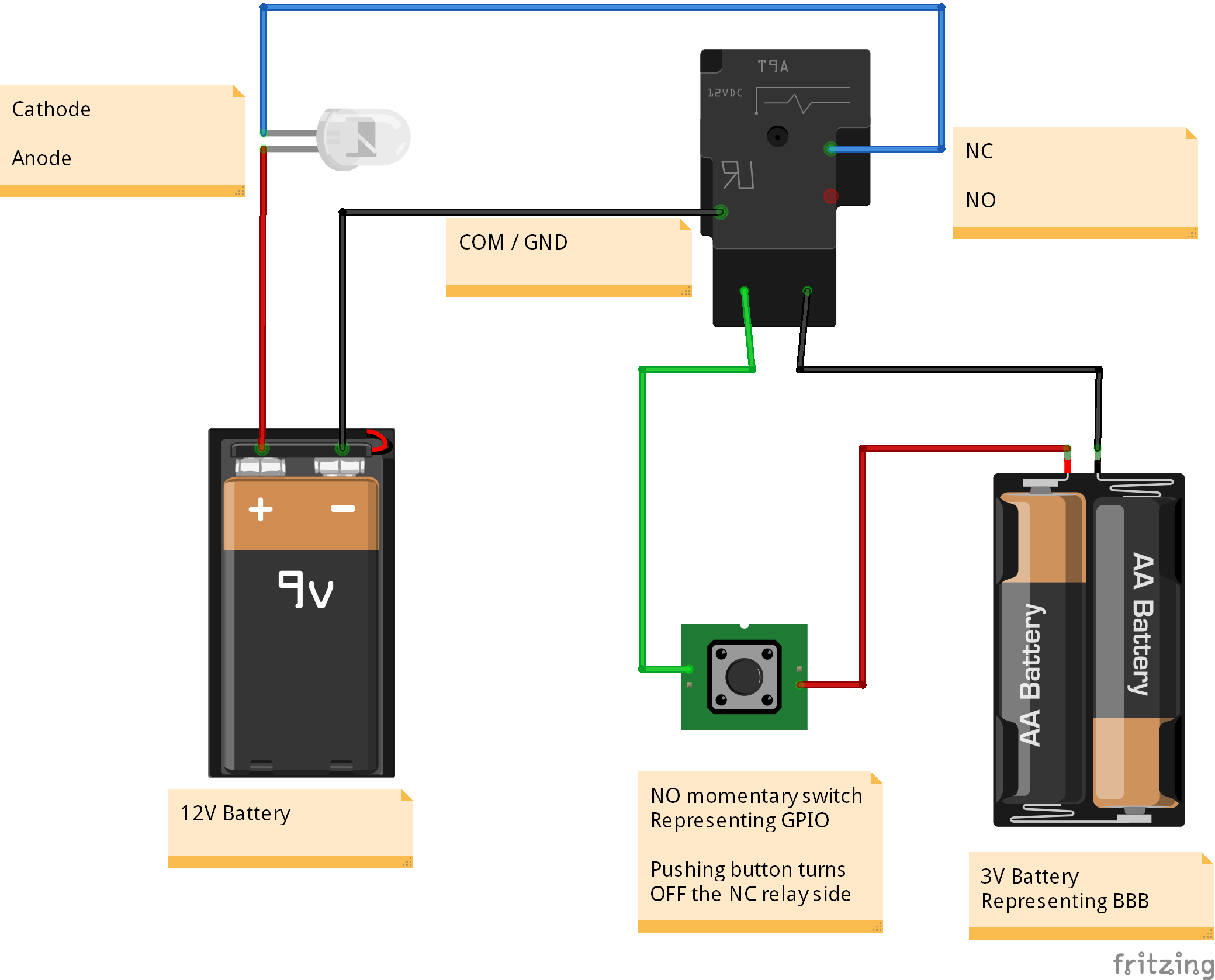
  Note that the relay does not provide its own voltage/current -- so if
you were trying to measure voltage by connecting the probes to COM and
either NC or NO, you will only see 0.00V. In order to see a voltage, you
MUST have a battery in the circuit.

  B- to COM
  meter "black" to NC (or NO)
  meter "red" to B+

  If using the NC, the meter should read the battery voltage, while NO
reads 0.0V. Running a program to toggle the relay should result in NC
showing 0.0V and NO showing battery voltage.

Recommend you obtain a collection of jumper wires with small alligator
clips...

https://www.adafruit.com/product/1008 (double-ended)
https://www.adafruit.com/product/3448 (single-ended, for breadboard
sockets)

  Unfortunately, the web site doesn't give enough information to tell
which side of the LED is GND and which is V+. I'm presuming the base is
polarized to fit some sort of automotive socket, but would then need to see
such a socket and how it is wired...