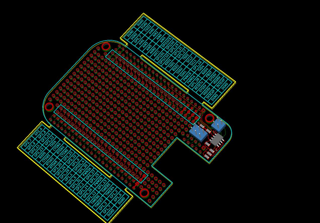
Attached is version 0.1 of my proto board cape. The "wings" with
signal names can be removed and then the cape will match the size of
BeagleBone.
Comments, ideas and paper-verification of the cape will be highly appreciated.
j.
flying_bone_v0.1_preview.pdf (149 KB)
Is it a single or stackable?
Gerald
Can be made stackable through connectors with long pins, like arduino
shields. I went yesterday through a paper copy of digikey's catalog,
but couldn't find any connectors that could be used to stack the
boards. Quick search at mouser wasn't helpful either. 4ucon has a
connector that could work (13430), but I have no idea who sells their
products in small quantities.
j.
I am working on the SRM and it will define the specification for the creation of capes in it.Take a look at Major League Electronics. They have the same connectors as used on the BeagleBone but with longer pins. Mount it the same as the BeagleBone with the longer pins coming out the bottom. Then it is stackable.
Gerald
Fellows,
I would also consider the flexible 0.1" pitch laminated ribbon
headers common in 90’s consumer electronics equipment.
They are low-cost and good enough for prototyping.
Can be inserted to femile sockets and come in many lengths.
They can also be easily soldered directly to plated-through holes.
I’ll try to find a few @ Mouser.
siñ
The will be fixed headers. SRM should be available tomorrow. I am working on it now.
Gerald
2011/11/6 Seppo Nikkilä <seppo.nikkila@innovativeideas.fi>
This is version 0.2, modified to follow the recommendations from the SRM.
Changes:
- Added a cutout to allow access to Reset button and the LEDs,
- Added footprint for the EEPROM and supporting elements.
- Removed battery connector
- Added a slot between the BB outline and the wings with descriptions,
to make chopping the wings off easier.
To save the space, EEPROM address is selected with jumpers instead of
switches. Stackable configurations can use 90deg headers.
Gerald, could you please critique the board? I have no way to verify
it and I'd like to release the design, so people could order proto
boards and start playing with BeagleBone as soon as it comes out. I
can send you gerbers if you need them.
j.
flying_bone_v0.2_preview.pdf (146 KB)
Hi Jacek,
This is great design and timing.
I surely want to have two of them once they become available.
Would you also consider to make a modified version that
has the original Beagleboard expansion connector on it.
This makes it possible to use all existing Beagleboard
expansion boards (and their drivers) with Beaglebone as well.
Please note that I didn’t check if all the Beagleboard
expansion signals are available on Beaglebone but
I suppose they are. So this is what we need to find out.
siñ
Hi Jacek,
This is great design and timing.
I surely want to have two of them once they become available.
Would you also consider to make a modified version that
has the original Beagleboard expansion connector on it.
This makes it possible to use all existing Beagleboard
expansion boards (and their drivers) with Beaglebone as well.
Please note that I didn't check if all the Beagleboard
expansion signals are available on Beaglebone but
I suppose they are. So this is what we need to find out.
There are pins that you signals that you could use to emulate the old
expansion header, but they would all be at 3.3V instead of 1.8V, which
means you might need level shifters--and, of course, you likely
already have level shifters on your original BeagleBoard
daughterboard. I'm not saying don't do it, but it might be slightly
less useful than you'd imagine.
Making a BeagleBoard version for BeagleBone is not really a good idea, but if you can add all th eelvel shifters that Jason mentioned it is possible.
Jacek,
Send me the gerbers and I will look at them later this week.
Gerald