RS-485 RTS drive RS-485 Tx-enable from Kernel

Hi
I have been struggling to get RS-485 Tx enable coms working on Beaglebone black.
As a newbie, Robert Nelson and Zmatt have been very helpful (and patient) with instructions to help me get this working.
I now have RTS and CTS enabled on my UART1 using BB-UART1-00A0.dts
I can drive RTS high and low from my CPP app, but the kernel does not automatically drive RTS for my RS-485 driver Tx-enable as I hoped.

I noted there was also a BB-UART4-RS485-00A0.dts file which pretty much models what I did to BB-UART1-00A0.dts except with UART4
The significant change was fragment 3 which has RS-485 related parameters which looked hopeful.

    fragment@3 {
        target = <&uart4>;
        __overlay__ {
            status = "okay";
            pinctrl-names = "default";
            pinctrl-0 = <&bb_uart4_rs485_pins>;
            rs485-rts-delay = <0 0>;

            rts-gpio = <&gpio3 19 1>; /*  GPIO_ACTIVE_HIGH>; */
            rs485-rts-active-high;
            linux,rs485-enabled-at-boot-time;
        };
    };

So I tried this adding the following to my /boot/uEnv.txt file

uboot_overlay_addr4=/lib/firmware/BB-UART1-00A0.dtbo
uboot_overlay_addr5=/lib/firmware/BB-UART4-RS485-00A0.dtbo

sudo ./show-pins.pl gives me:

P9.11                             28 T17 fast rx      6 uart 4 rxd       serial@481a8000 (pinmux_bb_uart4_rs485_pins)
P9.13                             29 U17 fast         6 uart 4 txd       serial@481a8000 (pinmux_bb_uart4_rs485_pins)
P9.27                            105 C13 fast    down 7 gpio 3.19        serial@481a8000 (pinmux_bb_uart4_rs485_pins)

I am not driving P9 pin 27 in my CPP app, hoping the Kernel will control it automatically but my scope shows it stays low even when I transmit.

I feel I am very close now but just need help to get this over the line.

Thanks
Michael
Hi Robert and Matt and anyone else following this.

I finally have it working on:

  • UART 1 using BB-UART1-00A0.dts
  • UART 4 using BB-UART4-00A0.dts

I had not configured the rs485conf struct using termios in my CPP test app properly.

If anyone follows this, please note:
RTS logic levels are backwards from what you might expect eg to set RTS high while transmitting you need:

  • rs485conf.flags &= ~(SER_RS485_RTS_ON_SEND);
  • rs485conf.flags |= (SER_RS485_RTS_AFTER_SEND);

You must also set the delays eg:
rs485conf.delay_rts_before_send = 1; /* Delay before send (milliseconds) /|
rs485conf.delay_rts_after_send = 0; /
Delay after send (milliseconds) */|

Thanks for your help - I really appreciate your time!
Best regards
Michael

I see in both cases, specifically the UART4 case, the regular overlay is used: BB-UART4-00A0.dts and not the RS485 Version (BB-UART4-RS485-00A0.dts) or the RTS/CTS version (BB-UART4-RTSCTS-00A0.dts). The regular overlay ignores RTS/CTS pins so they should not be able to be used.

In addition the UART4 RTS/CTS pins interfere with the HDMI/Video pins.

Given these facts I have a few questions

  1. How does the rs485 kernel software know which pin to pull to enable sending data?
  2. Are you using the default UART4 RTS pin (P8_33)?
  3. Did you also disable the video (disable_uboot_overlay_video=1) in /boot/uEnv.txt
  4. Do you have to recompile the Kernel with/wo the CONFIG_SERIAL_8250_OMAP=y remarked out?

I too need a RS485 port but I need an I2C and SPI buses as well so the UART4 seems to be the best route as I do not need HDMI out.

If anybody has a more in-depth and up-to-date understanding of how to make this work and how/why it does work, It would be appreciated. I am having a difficult time getting this to work with generic software like modpoll.

Hi Doug

I am far from an expert but I impart the following information from Robert which enabled me get it all working.

You must add the RTS and CTS line (CTS not required for RS-485) into the BB-UART4-RS485-00A0.dts file fragments 1 & 2 eg as follows:

/*

  • Copyright (C) 2013 CircuitCo
  • Virtual cape for UART4 on connector pins P9.13 P9.11
  • This program is free software; you can redistribute it and/or modify
  • it under the terms of the GNU General Public License version 2 as
  • published by the Free Software Foundation.
    */

/dts-v1/;
/plugin/;

#include <dt-bindings/board/am335x-bbw-bbb-base.h>
#include <dt-bindings/pinctrl/am33xx.h>

/ {
/*
* Helper to show loaded overlays under: /proc/device-tree/chosen/overlays/
*/
fragment@0 {
target-path=“/”;
overlay {

        chosen {
            overlays {
                BB-UART4-00A0 = __TIMESTAMP__;
            };
        };
    };
};

/*
 * Free up the pins used by the cape from the pinmux helpers.
 */
fragment@1 {
    target = <&ocp>;
    __overlay__ {
        P9_13_pinmux { status = "disabled"; };    /* uart4_txd */
        P9_11_pinmux { status = "disabled"; };    /* uart4_rxd */
        P8_33_pinmux { status = "disabled"; };
        P8_35_pinmux { status = "disabled"; };
    };
};

fragment@2 {
    target = <&am33xx_pinmux>;
    __overlay__ {
        bb_uart4_pins: pinmux_bb_uart4_pins {
            pinctrl-single,pins = <
                BONE_P9_13 (PIN_OUTPUT | MUX_MODE6)    // gpmc_wpn.uart4_txd_mux2
                BONE_P9_11 (PIN_INPUT  | MUX_MODE6)    // gpmc_wait0.uart4_rxd_mux2
                BONE_P8_33 (PIN_OUTPUT | MUX_MODE6)    // uart4_rtsn.uart4_rtsn
                BONE_P8_35 (PIN_INPUT | MUX_MODE6)    // uart4_ctsn.uart4_ctsn
            >;
        };
    };
};

fragment@3 {
    target = <&uart4>;
    __overlay__ {
        status = "okay";
        pinctrl-names = "default";
        pinctrl-0 = <&bb_uart4_pins>;
    };
};

};

Q1: See dts file source above.
Q2: Yes
Q3: Yes, and also disable_uboot_overlay_audio=1
You also need to map in the dtb0 files you are using eg in my case: i2c, Real time clock DS3231 (for DS1307) and the UARTx files as follows:

uboot_overlay_addr2=/lib/firmware/BB-I2C1-00A0.dtbo
uboot_overlay_addr3=/lib/firmware/BB-I2C1-RTC-DS3231.dtbo
uboot_overlay_addr4=/lib/firmware/BB-UART1-00A0.dtbo
uboot_overlay_addr5=/lib/firmware/BB-UART4-00A0.dtbo
uboot_overlay_addr6=/lib/firmware/BB-UART5-00A0.dtbo

disable_uboot_overlay_video=1
disable_uboot_overlay_audio=1

Q4 No I did not do this but you must also add the following text to /boot/uboot/uEnv.txt

optargs=quiet drm.debug=7 capemgr.enable_partno=BB-UART1,BB-UART2.BB-UART4,BB-UART5,BB-I2C1

You can test success (after reboot) using

cd /opt/scripts/device/bone
sudo ./show-pins.pl

eg result include the following lines

> P9.20 / cape i²c sda  94 D18 fast rx   0 uart 1 cts  serial@48022000 (pinmux_bb_uart1_pins)
> P9.19 / cape i²c scl  95 D17 fast      0 uart 1 rts  serial@48022000 (pinmux_bb_uart1_pins)
> P9.26                  96 D16 fast rx   0 uart 1 rxd  serial@48022000 (pinmux_bb_uart1_pins)
> P9.24                  97 D15 fast      0 uart 1 txd  serial@48022000 (pinmux_bb_uart1_pins)

After this if you enable RS-485 mode (see my last post before this for CPP), you can just transmit data and the Kernel will assert RTS to drive Tx-Enable automatically. I have checked this with my scope and it works exceptionally well.

Good luck!

1 Like

Well, I did as suggested and got the UART4-RS485 ‘kind of’ working. I assume we had to add the RTS (P8_33) back in because the UART driver cannot really use GPIO pins as the UART4-RS485.dts suggests is possible.

After making all the changes I still have to open UART4 as an RS232 port, trying to open as RS485 port in libmodbus fails. In addition I have to tell libmodbus to use the RTS signaling otherwise I get no RTS output at all.

Just before I made these changes I had got a working setup with UART4 && UART4-RTSCTS and using the above mentioned settings for libmodbus.

So with all the changes I have the same setup as using UART4 && UART4-RTSCTS.

I am not sure what went wrong but I appreciate the help. This is farther than I have gotten with the UART4-RS485 so far. But if it is not going to get me any closer than a stock version of the other overlays, I will revert back to them.

One last question, is it reasonable to say the stock UART4-RS485 overlay does not work? If so, is the reason it is not changed because there is just not enough manpower or something else?
I am not entirely grasping what the development practice and mindset is for this community.

Thanks again for the help.

Hi Doug

I am just a humble user like you, relaying my own experience. I am new to the Beagle too since last December so I can’t speak to the mindset of the community. From my own experience, the BBB is a well equipped low cost low spec SBC. The problem I have is with the documentation on how you do all of this stuff. It seems to be a collection of community experiences, but the problem is many articles are out of date.

Robert Nelson and Matt helped me get it going with the process I described to you, although using using the standard BB-UARTX-00A0.dts → .dtbo files

My understanding is that the overlay enabled us to get RTS and CTS handshake lines assigned to UARTS 1, 4 & 5.

Once this is set up at OS level, in my case my CPP app using termios can configure under software control, the UART for:

  • no flow control
  • software flow control
  • rts / cts hardware flow control (eg for RS-232)
  • RS-485 Tx-enable (controlled by the Kernel) (for RS-485)

…without changing the overlays

This makes sense to me. I hope it helps.

These properties are specific to the omap-serial driver which hasn’t been used for quite a while, its replacement being the 8250-omap driver. Here are my personal notes on the rs485-related DT properties of both drivers: rs485 DT properties - Pastebin.com

Yeah it’s broken, and there’s not really a proper replacement for it since 8250-omap doesn’t support using a random gpio for rts until kernel 5.3. And these overlays are kinda redundant anyway since rs485 mode is typically configured from userspace instead of using DT config.

Hi Matt
You said “…since 8250-omap doesn’t support using a random gpio for rts until kernel 5.3. …”
Do you mean we do not have to select expansion bus pins which also have an overlay map option for RTS?
The reason I ask is it would be nice to be able to also use UART2 with RTS for RS-485 by assigning RTS to a GPIO pin in the BB-UART2-00A0.dts file. Is this possible?

What I meant is that (in kernel 4.x, when using 8250-omap) you cannot use an artbirary pin as rts, the pin needs to actually have rts for that uart as one of its mux modes, e.g. for UART2 the only RTS pin is P8.38.

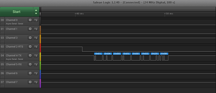
Hello, I am a new user of the BeagleBoard, and I need some help setting up a uart2_rs485.dts file. My custom BeagleBoard supports half-duplex connection in UART2, which means that when I set RST High, I can write, and when RST Low, I can read. I have created a UART2_RS485.dts file (the code above) that is almost working. The problem I have is when I test the port (as simple UART for now) with a script I wrote via a logic converter. As you can see in the picture, the RST gets low by the time my script starts running and gets back high after 1 second. The proper function should be when TX is sending data → RST HIGH / after data send, RTS LOW to receive data. As I mentioned before, I have attached the dts file, the test script, and the photo of the result I get. Can anyone help me with the dts? More information about pins in the dts file. Thank you in advance!
BB-UART2-RS485-00A4.dts (1,6 KB)
modbusv2.py (1,9 KB)

the main problem you’re having is that, as I’ve said earlier in this thread, enabling rs485 mode from DT is currently not supported and instead you need to enable it from userspace. You need to do e.g.:

serialPortSchneider.rs485_mode = serial.rs485.RS485Settings(rts_level_for_tx=False, rts_level_for_rx=True)

I’m not sure whether False means high or low (since rts is normally active-low) so it’s possible you need to invert the two levels.

Also, you should remove the rts-gpio and rs485-rts-active-high properties since

  1. as I’ve explained in this thread, these settings are specific to the omap-serial driver which is no longer in use
  2. both settings are wrong for your setup: you’re not using a GPIO as RTS, you’re using the actual RTS pin of the UART. Also, as my pastebin notes, rs485-rts-active-high; actually made the RTS active-low (contrary to the name).

At the time of writing this post, I made the following changes:

BB-UART2-RS485-00A5.dts (1,9 KB)
rts-activate.py (1,6 KB)

Through these changes, I was able to achieve almost perfect communication. However, the only issue I am facing is that when I receive a Modbus answer, I am getting 1 or 2 junk bytes at the front, and they are always 00. For now, I am trying to implement a solution where I throw the first byte if it is 00 when I receive an answer. However, I know that this approach is incorrect. Can you help me understand why this is happening?
I am going to try the DTS file as you suggested tomorrow, and if that succeeds, I will inform you. However, I do not believe that this is the solution.

Watching mainline, it looks like 485 is now working for the generic 8250 serial driver we enable by default, but you need to change the pinmux to normal gpio (mode7) (not ctsn/rtsn mode 6), and let the driver handle the i/o details…

Example: kernel/git/torvalds/linux.git - Linux kernel source tree and kernel/git/torvalds/linux.git - Linux kernel source tree

Regards,

using the actual RTS pin (in UART mode, not GPIO mode) is supported by 8250 since at least 4.19 though, while using GPIO mode definitely wasn’t yet.

Looking at his recent post it kinda looks like he might be using a really ancient kernel with omap-serial though?

Hello again, I managed to test what you suggested. However, the problem is that the suggested solution made the communication worse. First of all, it’s important to clarify that my system runs on Linux arm 4.19.94-ti-r42 & CONFIG_SERIAL_8250=y. If you need further information on this, please let me know. I made the changes you suggested in the dts file (as you can see in the attachment BB-UART2-RS485-00A6.dts (1,9 KB)), but after that, with and without the usage of rts-activate, the RTS signal remained at 0.

Hi Panos_Theof
Just sharing my experience as a user who got help from the experts above, once I had my overlay configured correctly, I still had to initialize the UART for RS-485 Tx-enable in my software application. In my case CPP as follows:

	struct serial_rs485 rs485conf;
	rs485conf.flags |= SER_RS485_ENABLED;
	rs485conf.flags &= ~(SER_RS485_RTS_ON_SEND);
	rs485conf.flags |= (SER_RS485_RTS_AFTER_SEND);
	rs485conf.flags |= (SER_RS485_RX_DURING_TX);
	rs485conf.delay_rts_before_send = 0; // Delay before send (milliseconds)
	rs485conf.delay_rts_after_send = 0; // Delay after send (milliseconds)
	if (ioctl (fd, TIOCSRS485, &rs485conf) > -1)	{
		Rs485KernelDriven = true;
	}

I hope this helps you.

1 Like

Hello Michaels.
Unfortunately, this is the code that I already have in the rts_activate.py script that I mentioned before. Therefore, it’s not very helpful to me. However, thank you for your response!

Hi Panos_Theof

I tried your implementation and I ran into the same issue and believe I have a fix.
The dts file I was using had the rxd line set to pull-down when it should have been set to pull-up.

The RS485 chip I am using sets the rxd line to high impedence when rts is active. Therefore, it is pulled down. When the rts is deactivated the rxd goes high again.

I believe this results in a series of bits that is: 0000 0000 1. WIth the settings I am using this resulted in 0x00 being read every time that rts is deactivated.

The change I made (when using UART1) was setting change from pin settings in the dts file from:
0x180 0x20 /* BONE_P9_26 (PIN_INPUT | MUX_MODE0) /
0x184 0x00 /
BONE_P9_24 (PIN_OUTPUT | MUX_MODE0) /
0x17c 0x00 /
BONE_P9_19 (PIN_OUTPUT | MUX_MODE0) /
to:
0x180 0x30 /
BONE_P9_26 (PIN_INPUT | MUX_MODE0) /
0x184 0x00 /
BONE_P9_24 (PIN_OUTPUT | MUX_MODE0) /
0x17c 0x00 /
BONE_P9_19 (PIN_OUTPUT | MUX_MODE0) */

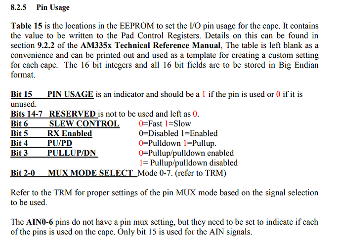
This page in the datasheet describes the pin usage settings. bit 4 describes whether the pin is pull up or pull down (pullup =1, pulldown = 0)

Hope this helps.