MichelC
September 2, 2025, 2:59am
1
I create an overlay for the RTC-10-click but it doesn’t work
What is wrong with it?
// SPDX-License-Identifier: GPL-2.0-only OR MIT
/*
 *
 * Copyright (C) 2025 Michel Catudal, https://suzielinux.com
 *
*/

/dts-v1/;
/plugin/;

#include "ti/k3-pinctrl.h"

/*
 * Helper to show loaded overlays under: /proc/device-tree/chosen/overlays/
 */
&{/chosen} {
	overlays {
		k3-j721e-beagleboneai64-rtc-i2c1-rv1.kernel = __TIMESTAMP__;
	};
};

&main_pmx0 {
    mcu_i2c1_pins_default: mcu_i2c1_pins_default {
        pinctrl-single,pins = <
        J721E_IOPAD(0xd4, PIN_INPUT, 0) /* SDA (G26) MCU_I2C1_SDA */
        J721E_IOPAD(0xd0, PIN_INPUT, 0) /* SCL (G27) MCU_I2C1_SCL */
        >;
    };
};

&mcu_i2c1 {
	status = "okay";
	pinctrl-names = "default";
	pinctrl-0 = <&mcu_i2c1_pins_default>;

	clock-frequency = <100000>;

	#address-cells = <1>;
	#size-cells = <0>;

	ds3231_rtc: ds3231_rtc {
		status = "okay";
		compatible = "maxim,ds3231";
		reg = <0x68>;
	};
};
First and foremost, I’d say tripple-backticks . It’s completely unreadable as presented.
If you want any serious scrutiny of your work, at least try
1 Like
MichelC:
but it doesn’t work
What doesn’t work about it? What are you expecting it todo?
Regards,
Much better already!
A few things to check:
Does your overlay even get loaded?
Is your I2C bus visible to the kernel?
Is the rtc-ds1307.ko available in /usr/lib/modules/…
If yes, is i loaded? lsmod
… just a little to get you started.
MichelC
September 3, 2025, 2:23pm
5
Enter choice: 3
3:      microSD (default)
Retrieving file: /Image.gz
append: root=/dev/mmcblk1p3 ro rootfstype=ext4 resume=/dev/mmcblk1p2 rootwait net.ifnames=0 plymouth.enable=0 rd.plymouth=0
Retrieving file: /ti/k3-j721e-beagleboneai64.dtb
Retrieving file: /overlays/BONE-CAN4.dtbo
Retrieving file: /overlays/BONE-4Relays.dtbo
Retrieving file: /overlays/k3-j721e-beagleboneai64-rtc-i2c1-rv1.dtbo
michel@BeagleBone:~$ dmesg | grep ds1307
[    1.857859] rtc-ds1307 4-0068: probe with driver rtc-ds1307 failed with error -110
I tried first with just the overlay and didn’t get any module loaded
I even tried to just disable the GPIO statements in it in my overlay as described in some beaglebone posts
There is no EEPROM settings for automatic recognition on this one
The I2C address would be 0x68
michel@BeagleBone:/boot$ sudo i2cdetect -y  -r 0
[sudo] Mot de passe de michel :
     0  1  2  3  4  5  6  7  8  9  a  b  c  d  e  f
00:                         -- -- -- -- -- -- -- --
10: -- -- -- 13 -- -- -- -- -- -- -- -- -- -- -- --
20: -- -- -- -- -- -- -- -- -- -- -- -- -- -- -- --
30: -- -- -- -- -- -- -- -- -- -- -- -- -- -- -- --
40: -- -- -- -- -- -- -- -- 48 49 4a 4b 4c 4d 4e 4f
50: UU UU -- -- -- -- -- -- -- -- -- -- -- -- -- --
60: -- -- -- -- -- -- -- -- -- -- -- -- -- -- -- --
70: -- -- -- -- -- -- -- --
MichelC
September 3, 2025, 2:39pm
6
It doesn’t load the module. I use the beaglebone AI64 on a test fixture I am doing for a French battery company. It is not connected on the internet, just local network. Without battery backup they would have to enter the time and date every time they run the program.
I had forgotten to add a clock with battery on my cape so I told them to provide me with a click board that has a clock. The nice thing about this one is that it doesn’t require an external clock.
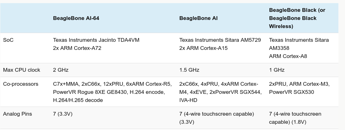
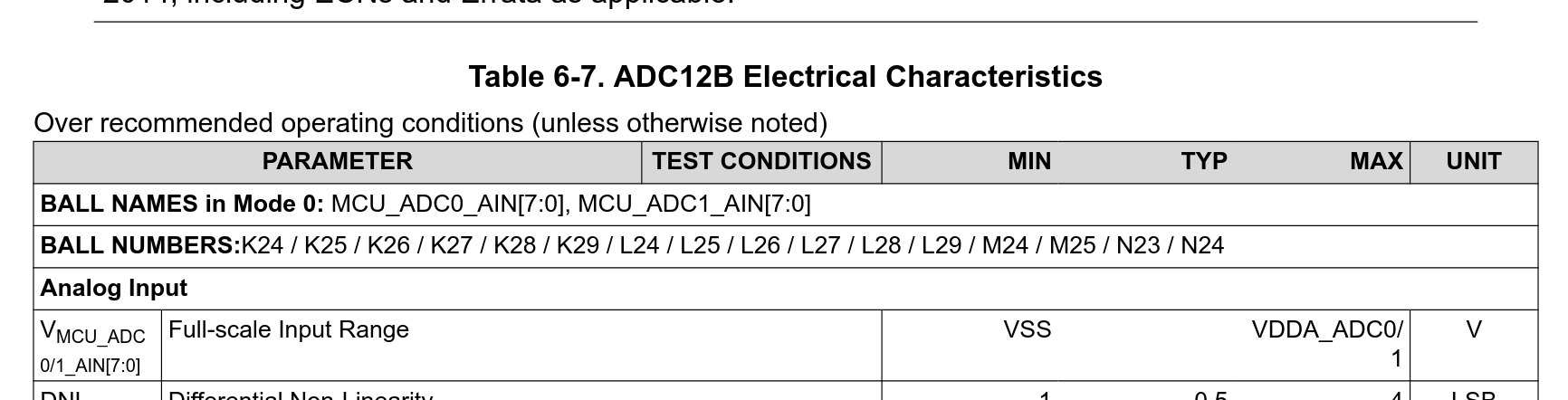
On the ADC nobody ever answered my question. Since my reading appear that the BBAI64 does support 3.3V I assumed this for my ADC code. What confused me is that the AI from google claims that it is 1.8V max but my reading say otherwise.
MichelC
September 3, 2025, 5:32pm
7
Why is it unreadeable? it is created identically to the way files like those are created, maybe the problem is with your browser.
All I did is cut and paste the content of the file. It looks perfect on my Firefox screen on gentoo.
MichelC
September 3, 2025, 5:44pm
8
It looks like you go the answer
Note that this message doesn’t show the star in the search, I have a star before the 1307
On my linux gentoo desktop1307 ”
On the beaglebone AI 64
I am using the debian released not long ago
root@BeagleBone:/usr/lib/modules# uname -r
I would rather use gentoo but this project is not for me but for a French Company.
It’s built in:
voodoo@la-i5-1135G7:/opt/github/buildscripts/bb.org/6.12.x/normal-arm64$ cat patches/defconfig | grep DRV_DS1307
CONFIG_RTC_DRV_DS1307=y
Regards,
Definitely 1.8V on the ADC pins… Generic I/O (non adc pins) is 3.3v.
MichelC:
&main_pmx0 {
    mcu_i2c1_pins_default: mcu_i2c1_pins_default {
        pinctrl-single,pins = <
        J721E_IOPAD(0xd4, PIN_INPUT, 0) /* SDA (G26) MCU_I2C1_SDA */
        J721E_IOPAD(0xd0, PIN_INPUT, 0) /* SCL (G27) MCU_I2C1_SCL */
        >;
    };
};
Pretty sure these both need to be PIN_INPUT_PULLUP/PIN_INPUT_PULLUP… also mcu_i2c1 might be on wkup_pmx0..
Starting TI’s tool… yeap..
&wkup_pmx0 {
	mcu_i2c1_pins_default: mcu_i2c1_pins_default {
		pinctrl-single,pins = <
			J721E_WKUP_IOPAD(0xd0, PIN_INPUT_PULLUP, 0) /* (G27) WKUP_GPIO0_8.MCU_I2C1_SCL */
			J721E_WKUP_IOPAD(0xd4, PIN_INPUT_PULLUP, 0) /* (G26) WKUP_GPIO0_9.MCU_I2C1_SDA */
		>;
	};
};
Regards,
4-0068: → so bus 4 with i2cdetect…
sudo i2cdetect -y -r 4
Regards,
MichelC
September 3, 2025, 11:39pm
14
Thanks, that fixes it, now I need to set it the right time.
michel@BeagleBone:~$ dmesg | grep rtc
Awesome! I’d say, you made it to the finish line…
MichelC
September 4, 2025, 6:47pm
16
MichelC:
cat /sys/bus/iio/devices/iio:device0/in_voltage
Theory isn’t always accurate
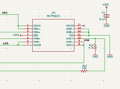
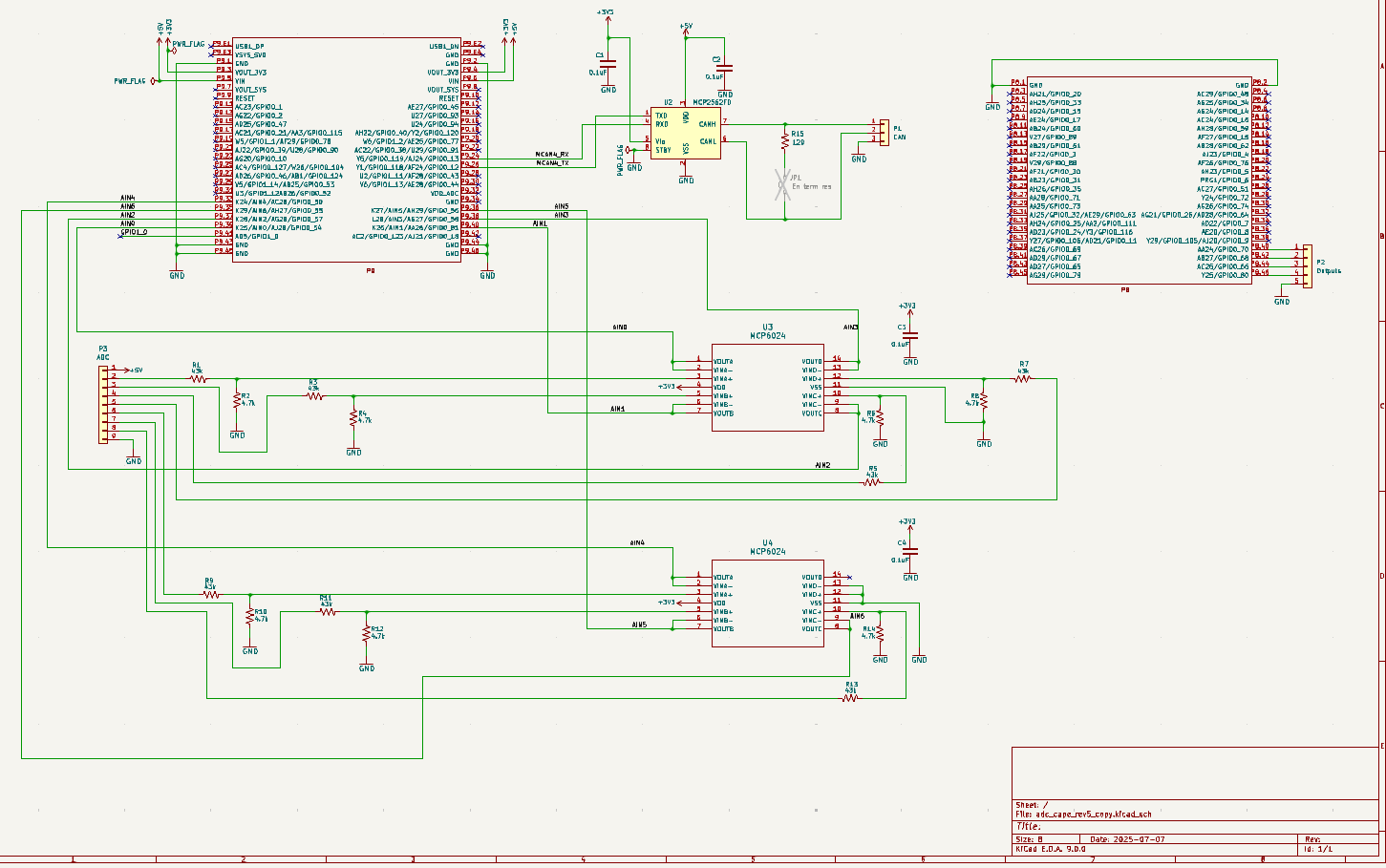
I put +12V across the input at R13
root@BeagleBone:/home/michel# cat /sys/bus/iio/devices/iio:device0/in_voltage6_raw
I read 1.21V at pin 8
12.33 * 4.7/47.7 = 1.2149 which is close
If the max voltage was 1.8V I would assume that I would read around 2752
The voltage scale is 0.439453125 which would give me 606 mV
I think that the beaglebone black is 1.8v and this one is 3.3V
If I put 24V input I get 2730 count with 2.4V on input
2730 * 0.439453125 = 1.2
How is that voltage scale calculated?
In the cnx article it says that the voltage is 3.3V and not 1.8V
In the datasheet is says 1.8/3.3V, likely 1.8V if the device is powered at 1.8V
The AI-64: TDA4VM:
The “AM57xx” BeagleBone AI, used an external ST ADC over i2c..
Regards,
MichelC
September 4, 2025, 11:51pm
18
I saw that but what I found out when I measured the signals and read inside Linux that I can read 2.4V which is higher than 1.8V
I used a 24V supply with a pot to test the ADC.
Since the voltage scale is read as 0.439453125 it would imply that the ref voltage is 1.8V
Is there something wrong in my design or an error in the Beaglebone Debian and specs?