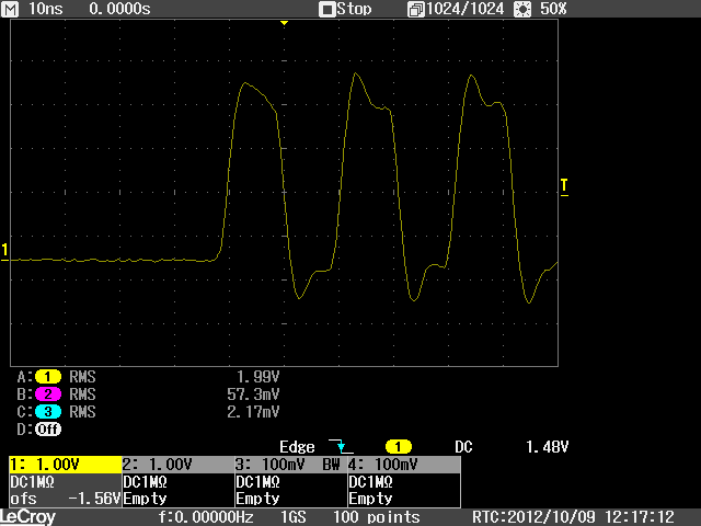
Does anybody have any sample waveforms of SDIO transactions? I’m trying to troubleshoot a WL1271 (LSR module, really) communications problem. One thing I noticed was that my SDIO CLK looks very sinusoidal. At first I thought it was a board problem (which it still may be) but I removed the cape and probed right at P8-21, using good scope practices (short lead, good ground, quality probe on a 1 GHz Lecroy).
It appears to me the clock is a sine wave (not a nice rectangular clock as I expected). I’m guessing this is for EMI control. It also appears that the data must be intended to be sampled on the falling edge of that sine wave somewhere.
Can anybody confirm this, or point me to some specs or timing diagrams? The LSR data sheet, as well as a general search of google, didn’t prove to be helpful. (Perhaps it’s a closed spec?)
–Chris
Do you use pull up in SDIO signal ?
You can try to pull up with 4.7k or 10k .
Not only the clock . but also 4 data pin , I suggest you use pull up them .
2012/10/9 Christopher Piggott <cpiggott@gmail.com>
Does anybody have any sample waveforms of SDIO transactions? I'm
trying to troubleshoot a WL1271 (LSR module, really) communications
problem. One thing I noticed was that my SDIO CLK looks very
sinusoidal. At first I thought it was a board problem (which it
still may be) but I removed the cape and probed right at P8-21, using
good scope practices (short lead, good ground, quality probe on a 1
GHz Lecroy).
Attached, hopefully it comes through, is a screen shot on a BeagleBone
A3 of the mmc0 clock line taken with a 200 MHz scope with a general
purpose 200 MHz probe and poor probe skills. Looks like a reasonable 50
MHz square wave, given my probe techniques and tools 
I'm pretty sure that everything broken out to the P8/P9 headers is NOT
length matched nor impedance controlled, at least not nearly as well as
the onboard peripherals are.
It appears to me the clock is a sine wave (not a nice rectangular
clock as I expected). I'm guessing this is for EMI control. It also
appears that the data must be intended to be sampled on the falling
edge of that sine wave somewhere.
Can anybody confirm this, or point me to some specs or timing
diagrams? The LSR data sheet, as well as a general search of google,
didn't prove to be helpful. (Perhaps it's a closed spec?)
For a point of reference, can you run a normal SD card in the slot? At
least then you'd help confirm if your cape or the SDIO card is the
issue. We have a custom cape with mmc1-clk on P8-21 and have no major
issues with running off an SD card there. Sorry, no scope plots of
that, although probably worth me checking...
-Andrew