Hi,
I’ve been proposing something very similar that would use a BBB or a PIC32. The reason for the PIC32 is the lack of I/O on the Beagle once you enable the HDMI or plug in one of those small 4.3" LCD displays.
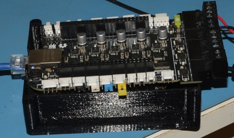
I already have a 4DCape (attached JPG) and a Replicape c/w with poorly functioning Manga Screen. I bought the newer Manga screen but as yet haven’t really done anything with it or the Replicape.
I’ve also got an earlier xylotex DB25 cape and a LogicSupply Serial cape. Unlike say the ISA bus on the original PC, nothing is really compatible so they can all plug in at the same time which makes sense because the BBB external connections aren’t really an expandable bus.
OK. So what does a CNC system need? I think it’s always better to first specify the needs and then see what processor fits rather than insist on a particular architecture and then shoehorn in the specifications to fit the target hardware.
- Either 4 or 5 axis step/dir.
a. At a minimum X,Y,Z, A and B(or C) and up to 500kHz step rates to handle some of the now low cost AC servos with 2500 line encoders.
- Spindle control in the form of two outputs:
a. PWM and Direction or
b. Step and Direction or
c. Relay Clockwise, Counter Clockwise.
- Spindle Quadrature encoder input
a. Differential A/B and Index high speed hardware for 2500 line encoders turning up to 3000 RPM.
- Home switch input for 4 or 5 axis (does a rotary require a home switch).
a. shared with Limit switch for each axis.
b. Open circuit means activated.
- Limit switch for the other end of each axis.
a. Open circuit means activated.
-
ESTOP input with ESTOP asserted when ESTOP not connected.
-
ENABLE output.
a. One active high
b. One active low.
- Coolant output control
a. Flood
b. Mist
-
General purpose output signals for power supply enables etc.
-
Charge Pump output that when stopped shuts off all outputs including ENABLE.
-
USB input for a pendant of some type
a. For USB stick for code or firmware updates.
-
Or at least Inputs for Quadrature encoder knob and a few buttons.
-
MODBus support with either RS232 or RS485
a. for something like a Homann Designs MODIO
b. Other MODBus end products for things like tool changers
- CAN bus with CANopen support
a. for expanding to other hardware like tool changers.
-
Ethernet connectivity.
-
Some sort of display. Size depending on what level of application is running on the BBB.
Point 16 is the interesting part. Should this be a small 4.3" to 7" LCD display serving as a rudimentary DRO and status display? Or should it be the entire AXIS interface or something between.
And with point 16 in mind, if the display makes the BBB into an intelligent power feed DRO controller to allow essentially manual operation on the mill then the Ethernet port could be used to connect a full size PC (laptop or workstation) running LinuxCNC/MachineKit with full graphical tool path display etc.
It’s already possible to buy a CNC controller for $200 to $300 from China with a 4.3" display, a bunch of buttons and a USB connection for loading G-Code. And there are some users who swear by that solution as the easiest and fastest way to get working. But they aren’t open source. They aren’t expandable.
To have all the above I/O requires a lot of pins. I’m not sure the BBB can do this all. Unless it uses 10Mhz SPI to a serial shift register latch to create 6 axis STEP/DIR/PWM for X,Y,Z,A,B and Spindle along with coolant outputs to a maximum of 16 outputs. Since SPI is in and out the system can just as easily hold a 16 bit latch that is shifted in at the same time holding the various inputs except for ESTOP and maybe a MACHINE ON switch.
Some of the features on the PMDX-126 break out board could be part of this cape. In fact the idea that perhaps a simple I/O bus structure be designed in is a really good idea. A bi-directional 8 bit bus with a 4 bit address bus along with RD/WR/ signals would allow LCD displays and other external add on devices. The PIC32 for example supports that sort of bus. I think the ARM on the Beagle does too but it may not be available.
So this cape would look a lot more like a PMDX-126 but be that large BoB cape for the Beagle. It would have the I/O and maybe even high voltage relays along with optically isolated I/O.
https://www.pmdx.com/PMDX-126
The photos show how the PMDX has an expansion bus and a set of connectors that are compatible for a smooth stepper.
Perhaps make the BBB the replacement for the Smooth Stepper and the cape the replacement for a much more extensive PMDX-126. And use the BBB Ethernet connection to be the interface, if CNC is wanted, to MachineKit or LinuxCNC or even maybe MACH4 too. Give the BBB cape a display output for rudimentary DRO and control information but for full CNC let a processor like Raspberry Pi4 or PC with much better decent HDMI control serve as the graphical and keyboard/mouse user input.
The need for the BBB to do everything just doesn’t exist anymore when that Pi4 only adds $50 to the price and the display/keyboard/mouse are fixed costs no matter what system is used.
Make the system stand alone and scalable so a user can first add just a motor to their X axis for power feed. Six monts later the Y axis for power feed. Then a year later the Z axis for power feed. When they swap in a 3 phase or AC servo motor onto the spindle they suddenly have on/off speed control and now the potential to add simple CNC operations. Some of those could even be local like the wizards in MACH3/4.
IMHO
John Dammeyer