Note: This problem is now solved. However, I posted it here in the event that someone encounters a similar issue
Description and symptom:
I had communication troubles when speeds greater than 125000 bit/s are used between an Ardupilot flight controller (running on BeagleBone Blue) and this amazing sensor: Here Flow - CubePilot.
In other words, speeds like 250000, 500000, 1000000 bit/s do not work.
For diagnostic purposes (I didn’t had any logic analyzer at this stage) I connected two identical BeagleBones Blue through CANH and CANL signals, putting an oscilloscope on both wires:

Note: the ground connection is not necessary.
The problems are:
- After sending roughly ten CAN-frames at 125000 bit/s, the SocketCAN interface does not work anymore (it hangs)
- I was unable to communicate in any way with SocketCAN using bitrates > 125000 bit/s
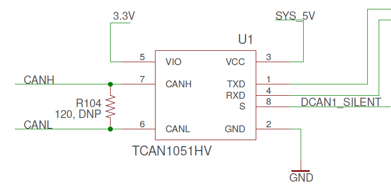
The devices are very close to each other; also in the TRM, it’s stated that bit rates up to 1 Mbit/s should be supported. Furthermore, I checked on the BeagleBone Blue schematic that the 120 Ω resistor is present:
Problem 1 demonstration:
Session 1 on beaglebone1:
root@beaglebone1:/home/debian# ip link set can0 up type can bitrate **125000**
root@beaglebone1:/home/debian# candump can0
Session 2 on beaglebone2:
root@beaglebone2:/home/debian# ip link set can0 up type can bitrate **125000**
root@beaglebone2:/home/debian# candump can0
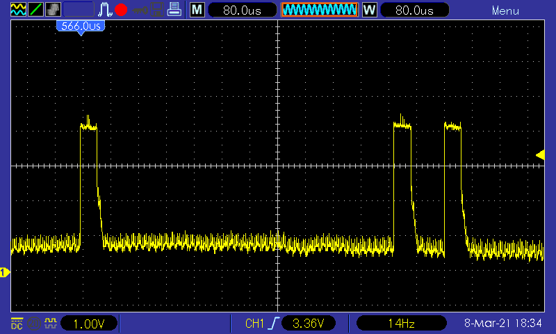
One can see that after the “ip link set command” each device sends periodically some pulses:
Session 3 on beaglebone1:
root@beaglebone1:/home/debian# cansend can0 5A1#00.01.02.03.04
Session 4 on beaglebone1:
Preformatted textroot@beaglebone2:/home/debian# cansend can0 5A1#00.01.02.03.04
Result:
Session 1 on beaglebone1:
root@beaglebone1:/home/debian# ip link set can0 up type can bitrate 125000
root@beaglebone1:/home/debian# candump can0
can0  5A1   [5]  00 01 02 03 04
can0  5A1   [5]  00 01 02 03 04
Session 2 on beaglebone2:
root@beaglebone2:/home/debian# ip link set can0 up type can bitrate 125000
root@beaglebone2:/home/debian# candump can0
can0  5A1   [5]  00 01 02 03 04
can0  5A1   [5]  00 01 02 03 04
After some ten CAN-frames sent with “cansend”, the communication is definitively lost: candump no longer shows anything. Moreover, the status of the interface changes from “UP,RUNNING,NOARP” to “UP,NOARP” (for “bus-off” state). This would suggest that too many errors occurred on the CAN bus:
root@beaglebone1:/home/debian# ip link set can0 up type can bitrate 125000
root@beaglebone1:/home/debian# ifconfig can0
can0: flags=193<UP,RUNNING,NOARP>  mtu 16
        unspec 00-00-00-00-00-00-00-00-00-00-00-00-00-00-00-00  txqueuelen 10  (UNSPEC)
        RX packets 2  bytes 16 (16.0 B)
        RX errors 0  dropped 0  overruns 0  frame 0
        TX packets 0  bytes 0 (0.0 B)
        TX errors 0  dropped 0 overruns 0  carrier 0  collisions 0
        device interrupt 51
In this case, after receiving just one frame, the error status occurred:
root@beaglebone1:/home/debian# candump can0
  can0  7DF   [8]  02 09 02 00 00 00 00 00
^C
root@beaglebone1:/home/debian# ifconfig can0
can0: flags=129<UP,NOARP>  mtu 16
        unspec 00-00-00-00-00-00-00-00-00-00-00-00-00-00-00-00  txqueuelen 10  (UNSPEC)
        RX packets 3  bytes 24 (24.0 B)
        RX errors 0  dropped 0  overruns 0  frame 0
        TX packets 1  bytes 8 (8.0 B)
        TX errors 0  dropped 0 overruns 0  carrier 0  collisions 0
        device interrupt 51
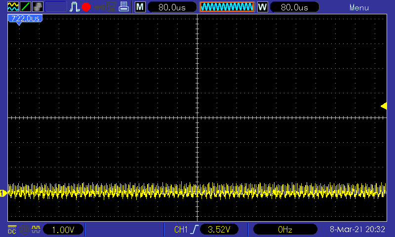
Also one can see on the scope that the devices don’t send anymore any pluses:
The interface can be reinitialized with “ip link set can0 down” and back “ip link set can0 up type can bitrate 125000”. Although an auto-restart can be set up with “ip link set can0 type can restart-ms 100” , some CAN frames are lost in case of bus error.
Problem 2 demonstration:
If I set: “ip link set can0 up type can bitrate 500000” on both devices and call “cansend can0 5A1#00.01.02.03.04” to send a sequence of bytes, candump does not show anything.
Other information:
Same behavior with 4.19.94-ti-r59 or with 4.19.94-ti-rt-r59 kernel.
root@beaglebone1:/opt/scripts/tools# ./version.sh
git:/opt/scripts/:[e4e4854ef8ff9ada5c85553376043ee7679167ca]
.....
The solution:
Once a logic analyzer (kindly lent by a friend) placed at the output of one of the devices (between CAN_L and CAN_H), I made a simple script sending continuously CAN frames:
#!/bin/bash

trap ctrl_c INT

function ctrl_c() {
        exit 0
}

while :
do
        #number=$(head -c8 /dev/urandom | od -A n -t x1 | cut -c2- | sed -e 's| |.|g')
        #cansend can0 5A1#${number}
        cansend can0 014#01
        #sleep 0.1
done
The “cansend can0 014#01” command sends the frame from https://en.wikipedia.org/wiki/CAN_bus:
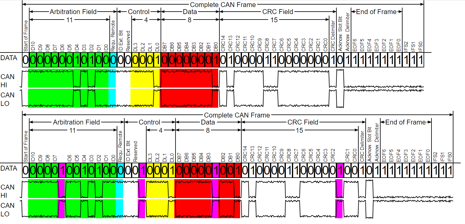
Despite that the analyzer decoded some correct frames, a high number of other frames have been marked as corrupted. After a closer inspection, the corruption was due to some parasitic glitches on the bus.
I tried to place a 120 Ω resistor between CANL and CANH and, after this, it worked perfectly even at 1000000 bit/s:

Everything suggested that the 120 Ω resistor from the diagram below was not present. Indeed, the termination resistors are needed to suppress reflections, but above all, to return the bus to its recessive or idle state (pull down).
After some searches on the “DNP” acronym, I learned that this stands for “do not populate” or “do not place” (components that are simply not placed on the board). Therefore, the schematic is correct and this makes sense because it’s up to the user to solder or not this resistor, depending on its application. For example, if the device is connected on a car’s CAN bus, the bus is already terminated at each end with 120 Ω resistors and therefore, the 120 Ω must not be present.
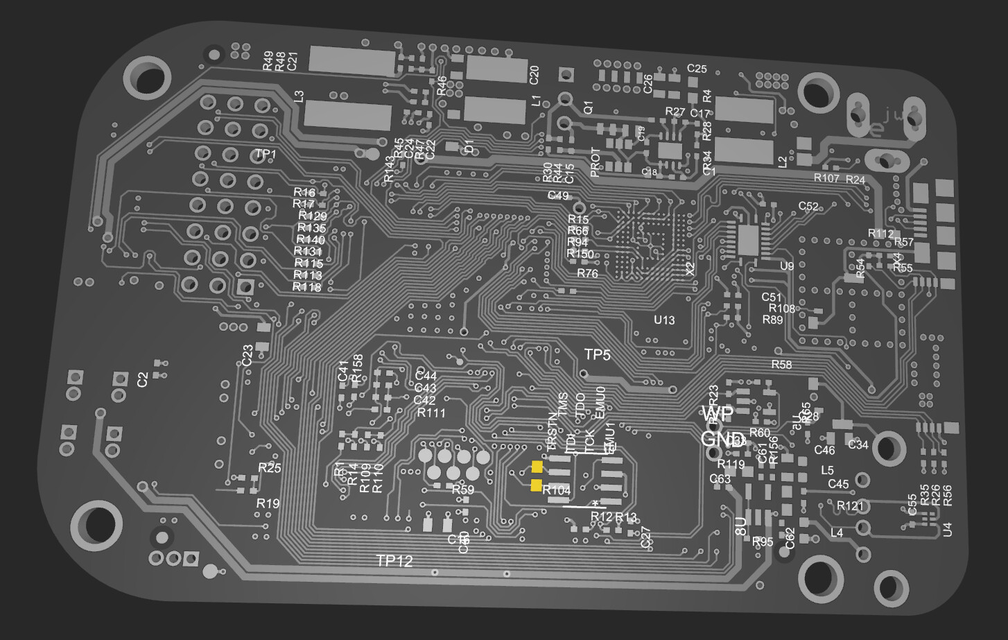
Below it’s the location (marked in yellow) where the R104 can be soldered on the PCB:
I finally made some communication tests between the boards and also with the Here Flow sensor and it works wonderfully! 
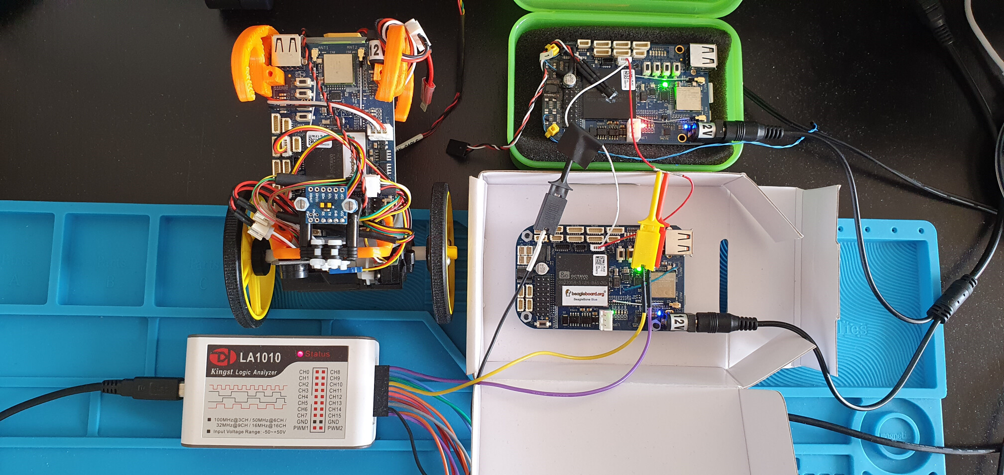
Below one can see my home made EduMIP equipped with a Here Flow (which provides the optical flow and rangefinder functions), a GY-53L1 Laser Distance ToF Sensor (anti-collision function), a YwRobot Active Buzzer Module and a LED headlight for the optical flow:
PS: The home made EduMIP’s motors and encoders assembly is from here or from here, using the encoders schematic below:
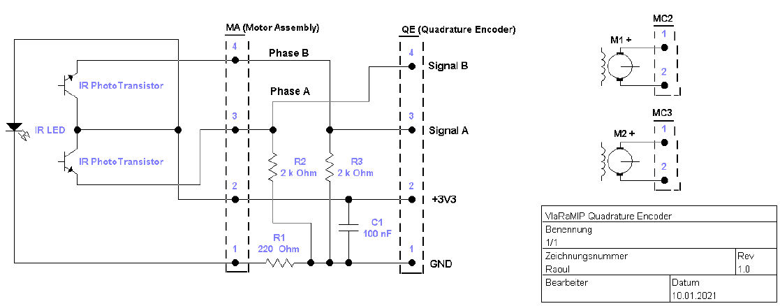
The other parts have been made on a 3D printer.
Hope this helps!!  ,
,  Vlad
Vlad
