I’m brand new to using SPI and trying to connect an LCD (Digital Visions DOGM128-6 Graphic) to a BeagleBone Black and do a basic “Hi BBB” message on the display with C. I’m starting to use Bullseye. I have wired up the display as follows:
BB → Display
P9_15 (GPIO) → A0/Pin38
P9_21 (spi) → SI / Pin 36
P9_22(spi_sclk) → CLK/SCL /pin 37
I am writing in C.
Here’s the output of beagle-version
root@BeagleBone:/home/debian/projects/APSDev# beagle-version
eeprom:[A335BNLT00C02411SBB02285]
model:[TI_AM335x_BeagleBone_Black]
dogtag:[BeagleBoard.org Debian Bullseye IoT Image 2023-09-02]
bootloader:[microSD-(push-button)]:[/dev/mmcblk0]:[U-Boot SPL 2022.04-ge0d31da5 (Aug 04 2023 - 18:48:26 +0000)]:[location: dd MBR]
bootloader:[eMMC-(default)]:[/dev/mmcblk1]:[U-Boot SPL 2019.04-00002-gc9b3922522 (Aug 24 2020 - 16:42:18 -0500)]:[location: dd MBR]
bootloader:[eMMC-(default)]:[/dev/mmcblk1]:[U-Boot 2019.04-00002-gc9b3922522]:[location: dd MBR]
UBOOT: Booted Device-Tree:[am335x-boneblack-uboot-univ.dts]
UBOOT: Loaded Overlay:[BB-ADC-00A0.kernel]
UBOOT: Loaded Overlay:[BB-BONE-eMMC1-01-00A0.kernel]
UBOOT: Loaded Overlay:[BB-I2C2-RTC-DS3231]
UBOOT: Loaded Overlay:[BB-SPIDEV1-00A0]
kernel:[5.10.168-ti-r82]
nodejs:[v12.22.12]
/boot/uEnv.txt Settings:
uboot_overlay_options:[enable_uboot_overlays=1]
uboot_overlay_options:[uboot_overlay_addr4=/lib/firmware/BB-W1_P9.12-00A0.dtbo]
uboot_overlay_options:[uboot_overlay_addr5=/lib/firmware/BB-I2C2-RTC-DS3231.dtbo]
uboot_overlay_options:[uboot_overlay_addr6=/lib/firmware/BB-SPIDEV1-00A0.dtbo]
uboot_overlay_options:[disable_uboot_overlay_video=1]
uboot_overlay_options:[disable_uboot_overlay_audio=1]
uboot_overlay_options:[enable_uboot_cape_universal=1]
pkg check: to individually upgrade run: [sudo apt install --only-upgrade <pkg>]
pkg:[bb-cape-overlays]:[4.14.20210821.0-0~bullseye+20210821]
pkg:[bb-customizations]:[1.20240119.0-0~bullseye+20240119]
pkg:[bb-usb-gadgets]:[1.20240717.0-0~bullseye+20240717]
pkg:[bb-wl18xx-firmware]:[1.20230703.0-0~bullseye+20240703]
pkg:[kmod]:[28-1]
WARNING:pkg:[librobotcontrol]:[NOT_INSTALLED]
pkg:[firmware-ti-connectivity]:[20210315-3]
groups:[debian : debian adm kmem dialout cdrom floppy audio dip video plugdev users systemd-journal input render bluetooth netdev i2c gpio admin tisdk weston-launch cloud9ide]
cmdline:[console=ttyS0,115200n8 bone_capemgr.uboot_capemgr_enabled=1 root=/dev/mmcblk0p1 ro rootfstype=ext4 rootwait coherent_pool=1M net.ifnames=0 lpj=1990656 rng_core.default_quality=100 quiet]
dmesg | grep remote
[   12.972301] remoteproc remoteproc0: wkup_m3 is available
[   43.861187] remoteproc remoteproc0: powering up wkup_m3
[   43.861229] remoteproc remoteproc0: Booting fw image am335x-pm-firmware.elf, size 217148
[   43.861537] remoteproc remoteproc0: remote processor wkup_m3 is now up
[   59.897907] remoteproc remoteproc1: 4a334000.pru is available
[   59.922567] remoteproc remoteproc2: 4a338000.pru is available
dmesg | grep pru
[   59.897907] remoteproc remoteproc1: 4a334000.pru is available
[   59.922567] remoteproc remoteproc2: 4a338000.pru is available
dmesg | grep pinctrl-single
[   12.356102] pinctrl-single 44e10800.pinmux: 142 pins, size 568
dmesg | grep gpio-of-helper
[   12.357927] gpio-of-helper ocp:cape-universal: Failed to get gpio property of 'P8_03'
[   12.357958] gpio-of-helper ocp:cape-universal: Failed to create gpio entry
[   13.286115] gpio-of-helper ocp:cape-universal: Allocated GPIO id=0 name='P8_03'
[   13.286418] gpio-of-helper ocp:cape-universal: Allocated GPIO id=1 name='P8_04'
[   13.286623] gpio-of-helper ocp:cape-universal: Allocated GPIO id=2 name='P8_05'
[   13.286828] gpio-of-helper ocp:cape-universal: Allocated GPIO id=3 name='P8_06'
[   13.287315] gpio-of-helper ocp:cape-universal: Allocated GPIO id=4 name='P8_07'
[   13.287547] gpio-of-helper ocp:cape-universal: Allocated GPIO id=5 name='P8_08'
[   13.287757] gpio-of-helper ocp:cape-universal: Allocated GPIO id=6 name='P8_09'
[   13.288100] gpio-of-helper ocp:cape-universal: Allocated GPIO id=7 name='P8_10'
[   13.288321] gpio-of-helper ocp:cape-universal: Allocated GPIO id=8 name='P8_11'
[   13.288536] gpio-of-helper ocp:cape-universal: Allocated GPIO id=9 name='P8_12'
[   13.288848] gpio-of-helper ocp:cape-universal: Allocated GPIO id=10 name='P8_13'
[   13.289059] gpio-of-helper ocp:cape-universal: Allocated GPIO id=11 name='P8_14'
[   13.289252] gpio-of-helper ocp:cape-universal: Allocated GPIO id=12 name='P8_15'
[   13.289460] gpio-of-helper ocp:cape-universal: Allocated GPIO id=13 name='P8_16'
[   13.289661] gpio-of-helper ocp:cape-universal: Allocated GPIO id=14 name='P8_17'
[   13.289864] gpio-of-helper ocp:cape-universal: Allocated GPIO id=15 name='P8_18'
[   13.290067] gpio-of-helper ocp:cape-universal: Allocated GPIO id=16 name='P8_19'
[   13.290255] gpio-of-helper ocp:cape-universal: Allocated GPIO id=17 name='P8_20'
[   13.290459] gpio-of-helper ocp:cape-universal: Allocated GPIO id=18 name='P8_21'
[   13.290667] gpio-of-helper ocp:cape-universal: Allocated GPIO id=19 name='P8_22'
[   13.290869] gpio-of-helper ocp:cape-universal: Allocated GPIO id=20 name='P8_23'
[   13.291066] gpio-of-helper ocp:cape-universal: Allocated GPIO id=21 name='P8_24'
[   13.291252] gpio-of-helper ocp:cape-universal: Allocated GPIO id=22 name='P8_25'
[   13.291482] gpio-of-helper ocp:cape-universal: Allocated GPIO id=23 name='P8_26'
[   13.291688] gpio-of-helper ocp:cape-universal: Allocated GPIO id=24 name='P8_27'
[   13.292015] gpio-of-helper ocp:cape-universal: Allocated GPIO id=25 name='P8_28'
[   13.292246] gpio-of-helper ocp:cape-universal: Allocated GPIO id=26 name='P8_29'
[   13.292439] gpio-of-helper ocp:cape-universal: Allocated GPIO id=27 name='P8_30'
[   13.292644] gpio-of-helper ocp:cape-universal: Allocated GPIO id=28 name='P8_31'
[   13.292860] gpio-of-helper ocp:cape-universal: Allocated GPIO id=29 name='P8_32'
[   13.293058] gpio-of-helper ocp:cape-universal: Allocated GPIO id=30 name='P8_33'
[   13.293271] gpio-of-helper ocp:cape-universal: Allocated GPIO id=31 name='P8_34'
[   13.293459] gpio-of-helper ocp:cape-universal: Allocated GPIO id=32 name='P8_35'
[   13.293664] gpio-of-helper ocp:cape-universal: Allocated GPIO id=33 name='P8_36'
[   13.293863] gpio-of-helper ocp:cape-universal: Allocated GPIO id=34 name='P8_37'
[   13.294064] gpio-of-helper ocp:cape-universal: Allocated GPIO id=35 name='P8_38'
[   13.294267] gpio-of-helper ocp:cape-universal: Allocated GPIO id=36 name='P8_39'
[   13.294468] gpio-of-helper ocp:cape-universal: Allocated GPIO id=37 name='P8_40'
[   13.294684] gpio-of-helper ocp:cape-universal: Allocated GPIO id=38 name='P8_41'
[   13.294898] gpio-of-helper ocp:cape-universal: Allocated GPIO id=39 name='P8_42'
[   13.295093] gpio-of-helper ocp:cape-universal: Allocated GPIO id=40 name='P8_43'
[   13.295315] gpio-of-helper ocp:cape-universal: Allocated GPIO id=41 name='P8_44'
[   13.295520] gpio-of-helper ocp:cape-universal: Allocated GPIO id=42 name='P8_45'
[   13.295712] gpio-of-helper ocp:cape-universal: Allocated GPIO id=43 name='P8_46'
[   13.296017] gpio-of-helper ocp:cape-universal: Allocated GPIO id=44 name='P9_11'
[   13.296232] gpio-of-helper ocp:cape-universal: Allocated GPIO id=45 name='P9_12'
[   13.296444] gpio-of-helper ocp:cape-universal: Allocated GPIO id=46 name='P9_13'
[   13.296685] gpio-of-helper ocp:cape-universal: Allocated GPIO id=47 name='P9_14'
[   13.296884] gpio-of-helper ocp:cape-universal: Allocated GPIO id=48 name='P9_15'
[   13.297088] gpio-of-helper ocp:cape-universal: Allocated GPIO id=49 name='P9_16'
[   13.297277] gpio-of-helper ocp:cape-universal: Allocated GPIO id=50 name='P9_17'
[   13.297483] gpio-of-helper ocp:cape-universal: Allocated GPIO id=51 name='P9_18'
[   13.297692] gpio-of-helper ocp:cape-universal: Allocated GPIO id=52 name='P9_19'
[   13.297886] gpio-of-helper ocp:cape-universal: Allocated GPIO id=53 name='P9_20'
[   13.298091] gpio-of-helper ocp:cape-universal: Allocated GPIO id=54 name='P9_21'
[   13.298311] gpio-of-helper ocp:cape-universal: Allocated GPIO id=55 name='P9_22'
[   13.298551] gpio-of-helper ocp:cape-universal: Allocated GPIO id=56 name='P9_23'
[   13.298763] gpio-of-helper ocp:cape-universal: Allocated GPIO id=57 name='P9_24'
[   13.299267] gpio-of-helper ocp:cape-universal: Allocated GPIO id=58 name='P9_25'
[   13.299509] gpio-of-helper ocp:cape-universal: Allocated GPIO id=59 name='P9_26'
[   13.299727] gpio-of-helper ocp:cape-universal: Allocated GPIO id=60 name='P9_27'
[   13.300045] gpio-of-helper ocp:cape-universal: Allocated GPIO id=61 name='P9_28'
[   13.300284] gpio-of-helper ocp:cape-universal: Allocated GPIO id=62 name='P9_29'
[   13.300490] gpio-of-helper ocp:cape-universal: Allocated GPIO id=63 name='P9_30'
[   13.300701] gpio-of-helper ocp:cape-universal: Allocated GPIO id=64 name='P9_31'
[   13.300928] gpio-of-helper ocp:cape-universal: Allocated GPIO id=65 name='P9_41'
[   13.301127] gpio-of-helper ocp:cape-universal: Allocated GPIO id=66 name='P9_91'
[   13.301335] gpio-of-helper ocp:cape-universal: Allocated GPIO id=67 name='P9_42'
[   13.301525] gpio-of-helper ocp:cape-universal: Allocated GPIO id=68 name='P9_92'
[   13.301537] gpio-of-helper ocp:cape-universal: ready
dmesg | grep wlcore
lsusb
Bus 001 Device 002: ID 0846:9030 NetGear, Inc. WNA1100 Wireless-N 150 [Atheros AR9271]
Bus 001 Device 001: ID 1d6b:0002 Linux Foundation 2.0 root hub
END
Here is the output from config-pin
root@BeagleBone:/home/debian/projects/APSDev# config-pin -q P9_21

Current mode for P9_21 is:     spi

root@BeagleBone:/home/debian/projects/APSDev# config-pin -q P9_22

Current mode for P9_22 is:     spi_sclk

root@BeagleBone:/home/debian/projects/APSDev# config-pin -q P9_15

Current mode for P9_15 is:     gpio
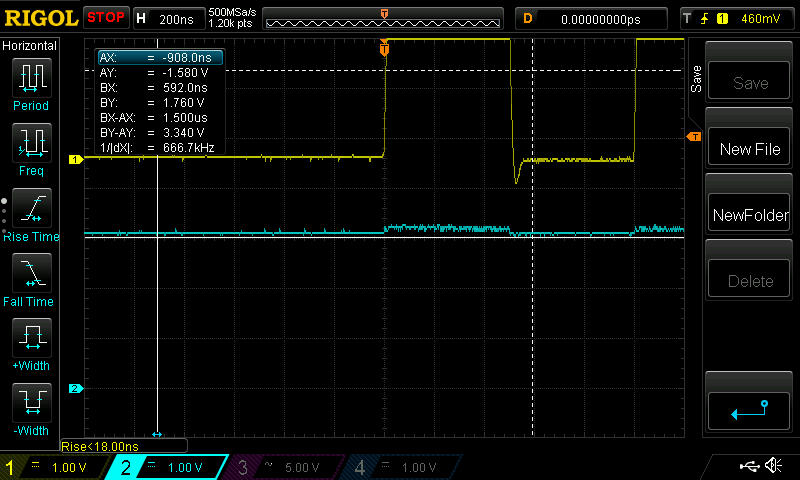
I have connected a scope to each line one at a time (just one channel on the scope in use)
When I run my program, the AO line (P9_15) toggles as it should.
But I never see any activity from P9_21 or P9_22. And nothing shows on the display.
Here’s my code for the ARM side.
#include <stdio.h>
#include <fcntl.h>
#include <unistd.h>
#include <sys/ioctl.h>
#include <linux/spi/spidev.h>
#include <gpiod.h>
#include <string.h>
#include <sys/types.h>

#define SPI_DEVICE "/dev/spidev1.0"
#define GPIO_CHIP "gpiochip1"
#define GPIO_A0 16 // P9-15 (GPIO1_16)
#define WIDTH 128
#define HEIGHT 64

static int spi_fd;
static struct gpiod_line *a0_line;

void spi_write(u_int8_t *data, size_t len, int is_data) {
    if (gpiod_line_set_value(a0_line, is_data) < 0) {
        perror("Failed to set A0");
        return;
    }
    struct spi_ioc_transfer tr = {
        .tx_buf = (unsigned long)data,
        .len = len,
        .speed_hz = 1000000,
        .bits_per_word = 8,
    };
    if (ioctl(spi_fd, SPI_IOC_MESSAGE(1), &tr) < 0) {
        perror("SPI write failed");
    }
}

void init_display() {
    u_int8_t init[] = {
        0xA2, // Bias 1/9
        0xA0, // ADC select
        0xC8, // COM reverse
        0xA6, // Display normal
        0xA4, // All points off
        0x40, // Start line 0
        0x2F, // Power control: all on
        0x27, // V0 regulator (1:5)
        0x81, 0x20, // Contrast
        0xAF, // Display on
    };
    spi_write(init, sizeof(init), 0);
    usleep(100000); // 100ms delay
}

void clear_display() {
    u_int8_t buf[WIDTH];
    memset(buf, 0, WIDTH);
    for (int page = 0; page < 8; page++) {
        u_int8_t cmd[] = {0xB0 + page, 0x10, 0x04};
        spi_write(cmd, 3, 0);
        spi_write(buf, WIDTH, 1);
    }
}

void draw_text(const char *text, int x, int page) {
    static const u_int8_t font[128][5] = {
        ['H'] = {0x1F, 0x04, 0x04, 0x1F, 0x00},
        ['I'] = {0x00, 0x1F, 0x00, 0x00, 0x00},
        [' '] = {0x00, 0x00, 0x00, 0x00, 0x00},
        ['B'] = {0x1F, 0x15, 0x15, 0x0A, 0x00},
    };
    u_int8_t cmd[] = {0xB0 + page, 0x10 + (x >> 4), 0x00 + (x & 0x0F)};
    spi_write(cmd, 3, 0);
    for (int i = 0; text[i]; i++) {
        spi_write((u_int8_t *)font[(unsigned char)text[i]], 5, 1);
    }
}

int main() {
    spi_fd = open(SPI_DEVICE, O_RDWR);
    if (spi_fd < 0) {
        perror("Failed to open SPI");
        return 1;
    }
    u_int8_t mode = SPI_MODE_0;
    u_int32_t spi_speed = 1000000;
    if (ioctl(spi_fd, SPI_IOC_WR_MODE, &mode) < 0) {
        perror("Failed to set SPI mode");
        close(spi_fd);
        return 1;
    }
    if (ioctl(spi_fd, SPI_IOC_WR_MAX_SPEED_HZ, &spi_speed) < 0) {
        perror("Failed to set SPI speed");
        close(spi_fd);
        return 1;
    }

    struct gpiod_chip *chip = gpiod_chip_open_by_name(GPIO_CHIP);
    if (!chip) {
        perror("Failed to open GPIO chip");
        close(spi_fd);
        return 1;
    }
    a0_line = gpiod_chip_get_line(chip, GPIO_A0);
    if (!a0_line) {
        perror("Failed to get A0 line");
        gpiod_chip_close(chip);
        close(spi_fd);
        return 1;
    }
    if (gpiod_line_request_output(a0_line, 0, 0) < 0) {
        perror("Failed to request A0 output");
        gpiod_line_release(a0_line);
        gpiod_chip_close(chip);
        close(spi_fd);
        return 1;
    }

    init_display();
    clear_display();
    draw_text("HI BBB", 10, 4);

    gpiod_line_release(a0_line);
    gpiod_chip_close(chip);
    close(spi_fd);
    return 0;
}
Not to confuse the issue, but ultimately, I want to use this with one of the PRUs.