Hello,
I’m working with the BeagleBone Black on a Yocto Kirkstone build and facing issues with accessing and exporting GPIOs, as typically done in the official Debian image for the BBB (using /sys/class/gpio/… or tools like gpioset/gpioget). Despite setting the GPIOs in the device tree, they don’t appear accessible for general-purpose scripts.
Has anyone encountered this issue or found a reliable way to access and export GPIOs in this setup?
Thanks in advance for any insights!
With the Yocto Kirkstone release and recent kernel updates, GPIO control on BeagleBoard devices like the BeagleBone Black has officially transitioned from the older sysfs interface to the gpiod (General Purpose Input/Output Daemon) interface. This change aligns with the deprecation of sysfs for GPIO, which is now largely unsupported and no longer maintained in new Linux kernels.
Why the Change? The sysfs interface for GPIO has been marked as deprecated for some time due to limitations in efficiency and scalability, especially as GPIO demands have evolved. The gpiod library, introduced as a modern alternative, provides several advantages:
- Improved Performance:
gpiod operations are generally faster, as they avoid the indirect file-system interaction used in sysfs.
- Better Support for Complex GPIO Management: With tools like
gpiodset and gpioget, gpiod supports multi-pin handling, debounce settings, and edge detection.
- Standardized Interface:
gpiod offers a more uniform interface for GPIO across various boards, making code more portable.
How to Use gpiod for GPIO on BeagleBoard Using gpiod is straightforward with commands that map closely to common GPIO tasks:
- Read a GPIO Pin:
gpioget gpiochip0 <pin_number>
- Set a GPIO Pin:
gpiodset gpiochip0 <pin_number> 1 (for HIGH) or 0 (for LOW)
For developers who previously relied on sysfs commands, the transition can involve only minor code adjustments to start using gpiod. There’s also the libgpiod C library if you’re integrating GPIO control directly in your applications.
Getting Started If you’re setting up your BeagleBoard with Yocto, adding gpiod is as simple as including it in your recipe with IMAGE_INSTALL_append = " libgpiod". You can then access GPIO functionality through the command line or integrate it directly into your applications using libgpiod.
For Developers and Contributors This transition represents a big step toward future-proofing GPIO management on Linux. While sysfs may still work on legacy systems, gpiod is now the preferred and supported path forward. Feel free to share your experiences and tips on the BeagleBoard forums to help other developers make a smooth transition.
I’ve already added IMAGE_INSTALL_append = " libgpiod" to my Yocto configuration, so gpiod tools like gpioget and gpioset are available on my BeagleBone Black running Yocto Kirkstone.
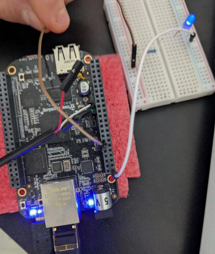
To clarify, I’m specifically testing the P9_12 pin (GPIO_60) from the P9 expansion header’s GPIO bank (see image below).
To identify the corresponding line, I ran:
gpioinfo gpiochip0 | grep -i p9_12
This showed:
line 28: "P9_12" unused output active-high
Following this, I tried toggling the pin’s value with:
gpioset gpiochip0 28=0
gpioset gpiochip0 28=1
However, when I check the value with:
gpioget gpiochip0 28
it always returns the same value, regardless of the previous gpioset command. I’ve confirmed that the device tree settings should support GPIO mode for this pin. Is there anything further I need to verify or configure to ensure proper functionality with gpiod? Any guidance on troubleshooting this would be greatly appreciated.
Thanks again!
Sounds to me like you haven’t set the correct pinmux for that pin or something else has grabbed it.
The gpioxxx commands assume that the GPIO pin is correctly routed from the peripheral to the outside. They don’t set the pin muxing in any way.
I am compiling kernel from:
github.com/beagleboard/linux.git
Checked-out at:
v6.1.80-ti-r34 (4ca9ea30768d58c8d4d56d03dd1eaf8c8feb7ef9)
So all the DTSs should be here:
github.com/beagleboard/linux/tree/v6.1.80-ti-r34/arch/arm/boot/dts
Ready for BBB pinmux exportation (from TI work…) , or am I wrong ?
The pinmuxs may be declared yes, but in the default devicetree that is loaded they may or may not be used. I could be wrong but I am pretty sure that the gpioxxx commands do not do anything with pin muxing, they just interact with the GPIO peripheral.
Somewhere you need to actually use a defined pinmux, typically with the pinctl-0 = <>; in a devicetree section.
Looking at the git repo there is a file that creates a load of pinsmuxs ( am335x-bone-common-univ.dtsi) . So for P9_12 there are 3 pinmuxes of interest named P9_12_gpio, P9_12_gpio_pu and P9_12_gpio_pd. The pu/pd refer to pullup and pulldown.
So you need to actually uses these. You can create your own overlay to add pinctl-0 = <&P9_12_gpio>; to the am33xx_pinmux section.
Now I am not 100% sure on the best way to do this. Generally an overlay overwrites parts in the loaded devicetree. You can’t remove entries and I am not sure if you can append. So if there is already a pinctl-0 = <>; value you might overwrite it with an overlay removing required settings, if that makes sense.
Documentation for all of this is a bit sparse. I have seen many overlays that use the ‘fragment’ key word and maybe this treats the overlay differently, appending if the value if it already exists rather than overwriting.
Hi @ricciolino ,
I’d be glad to help troubleshoot the device tree issue you’re facing. To get an exact replica of your environment and accurately debug the problem, would you mind sharing a few key details of your build setup? Here’s what would be helpful:
1. Bitbake Layers and Versions
Could you list all the Bitbake layers you’re using, including any custom or board-specific layers (e.g., meta-custom-imx8)? Please include:
- The
layer names, paths, and any specific branches or commit hashes if they are not on the main branch.
- Layer dependencies, especially if there are additional layers that your setup requires.
Running bitbake-layers show-layers and bitbake-layers show-recipes could also be helpful to spot any missing dependencies.
2. Build Configuration Files
If possible, could you share the contents of your local.conf and bblayers.conf (under conf/ in the build directory)? It would be great to know if you have specific machine configurations, toolchains, or unique environment settings.
3. Device Tree Source (.dts) and Custom Modifications
Could you share the path and any customizations made to the device tree source file (.dts)? If modifications were added to support specific peripherals or GPIO mappings, a code snippet or specific changes would help pinpoint potential issues.
4. Yocto Version and Toolchain Details
Please include the Yocto release you’re using (e.g., Kirkstone, Dunfell) and any toolchain or cross-compiler versions. Knowing the exact version helps ensure compatibility across the setup.
5. Kernel Version and Custom Kernel Configurations
Are you using a custom kernel configuration or specific kernel patches? If so, a brief list of patches or customizations applied could reveal why certain device tree entries might not load as expected.
Additional Details
Finally, any specific errors or warnings in the logs (dmesg output or journalctl) related to the device tree can help narrow down the root of the issue.
Thanks in advance for providing this setup info! With these details, I’ll be able to recreate your build environment and focus on getting your device tree working as intended.
Looking forward to your response.
I just tried adding the following to ‘am335x-boneblack.dts’:
&ocp {
    // Add pinmux configuration for P9_12 as GPIO output
    pinctrl_p9_12_gpio: P9_12_pinmux {
        pinctrl-single,pins = <0x078 0x07>;  // Set P9_12 to GPIO mode (mode 7)
    };

    P9_12_gpio_pin: helper {
        compatible = "bone-pinmux-helper";
        pinctrl-names = "default";
        pinctrl-0 = <&pinctrl_p9_12_gpio>;  // Apply P9_12 pinmux as GPIO
        status = "okay";
    };
};
But nothing changes…
root@beaglebone:~# gpioinfo  | grep -i p9_12
	line  28:      "P9_12"       unused   input  active-high
root@beaglebone:~# gpioget gpiochip0 28
1
root@beaglebone:~# gpioset gpiochip0 28=0
root@beaglebone:~# gpioget gpiochip0 28
1
root@beaglebone:~#
I also tried to build a BB-P9_12-GPIO-00A0.dtso overlay using this dtso as source:
// SPDX-License-Identifier: GPL-2.0-only
/*
 * Overlay to configure P9_12 as GPIO output on BeagleBone Black
 */

/dts-v1/;
/plugin/;

#include <dt-bindings/gpio/gpio.h>
#include <dt-bindings/pinctrl/am33xx.h>

/* Helper to show loaded overlays under: /proc/device-tree/chosen/overlays/ */
&{/chosen} {
    overlays {
        BB-P9_12-GPIO-00A0.kernel = __TIMESTAMP__;
    };
};

&am33xx_pinmux {
    p9_12_gpio_pin: pinmux_p9_12_gpio_pin {
        pinctrl-single,pins = <
            AM33XX_PADCONF(AM335X_PIN_GPMC_BEN1, PIN_OUTPUT_PULLUP, MUX_MODE7) /* P9_12 as GPIO */
        >;
    };
};

&ocp {
    p9_12_gpio_helper: helper {
        compatible = "bone-pinmux-helper";
        pinctrl-names = "default";
        pinctrl-0 = <&p9_12_gpio_pin>;
        status = "okay";
    };
};
I can confirm the overlay is loaded at u-boot:
Retrieving file: /extlinux/extlinux.conf
1:	Poky (Yocto Project Reference Distro)
Retrieving file: /extlinux/../zImage
append: root=/dev/mmcblk0p2 rootwait rw earlycon console=ttyO0,115200n8,115200 audit=0
Retrieving file: /extlinux/../am335x-boneblack.dtb
Retrieving file: /extlinux/../BB-P9_12-GPIO-00A0.dtbo
Kernel image @ 0x82000000 [ 0x000000 - 0xc04200 ]
## Flattened Device Tree blob at 88000000
   Booting using the fdt blob at 0x88000000
Working FDT set to 88000000
   Loading Device Tree to 8ffe2000, end 8fffffff ... OK
Working FDT set to 8ffe2000

Starting kernel ...
But still I cannot toggle the P9_12 (GPIO 28) value:
root@beaglebone:~# gpioget gpiochip0 28
1
root@beaglebone:~# gpioset gpiochip0 28=0
root@beaglebone:~# gpioget gpiochip0 28
1
root@beaglebone:~#
Might be nothing but have you looked at am335x-bone-common-univ.dtsi ?
The macros there for configuring GPIOS are - NOTE the INPUT_EN flag
	BONE_PIN(P9_12, default, P9_12(PIN_OUTPUT_PULLUP | INPUT_EN | MUX_MODE7))
	BONE_PIN(P9_12, gpio, P9_12(PIN_OUTPUT | INPUT_EN | MUX_MODE7))
	BONE_PIN(P9_12, gpio_pu, P9_12(PIN_OUTPUT_PULLUP | INPUT_EN | MUX_MODE7))
	BONE_PIN(P9_12, gpio_pd, P9_12(PIN_OUTPUT_PULLDOWN | INPUT_EN | MUX_MODE7))
Hi @benedict.hewson ,
Thank you very much for the suggestion! I’ve looked into the am335x-bone-common-univ.dtsi file and the macros you mentioned for configuring GPIOs. However, I’m not very familiar with DTS syntax or how these configurations work behind the scenes. Could you please provide a complete example of a DTSO file to set up P9_12 as a GPIO with the specific settings you suggested?
Thanks again for the help!
They are just a bunch of macros that expand into pinmux clauses. Takes a bit to get your head around it. However the important bit and perhaps partly what is giving you issues is the INPUT_EN flag, but in the datasheet this refers to the RX_ACTIVE bit I think. This bit enable inputs on the pin. If you are only using the pin as an output this does not matter, but you are trying to read the GPIO pin using gpioget. But in your overlay you are not enabling the RXACTIVE flag. In which case gpioget weill not be able to read the pin.
Read the AM335x data sheet for the Pad Control Registers.
But that only impacts using the GPIO port as an input. Using the GPIO as an output should work though.
Are you actually checking if you can toggle the pin or are you relying on the gpioget to check that status ?
Also running gpioget after gpioset will not necessarily return the state you wrote. You are in effect changing the GPIO direction from output to input and reading the state of the pin, not of the output register. In some mircos you can read a gpio output pin to return what you wrote, in others you can’t.
1 Like
Yes, I can actually check the PIN status as I have a LED attached to it and I have not seen it blinking (so the returned state of the gpioget command was coherent).
Anyway thanks for your suggetions, I’ll try to learn more on the DTS topic so that I’ll be able to mange things better!
Are you trying to pull the pin high and hold it there? In the example you’ve provided you will be pulling the pin momentarily. Its only gunna hold the pin state as long as gpioset is running.
If you are running the latest libgpiod release, you can now hold state detached from the calling process, otherwise, if you need libgpiod to hold the pin state for n time, you’ll need to do something like
gpioset -m time -s 30 gpiochip0 28=1
Hi @SuicidalLabRat ,
Thanks for your replay.
The command you provided actually works!!!
My goal was simply to programmatically set and get GPIO 28 pin value (blinking the LED attached to it), how can I make the gpioset tool to definitively set the GPIO pin to 0/1 value (without using any time and sec params)?
Im wrong here; the following is NOT available via the cmd line tools, yet.
If you are using a newer release of libgpiod (>2.0?), which is likely if you are running a recent kernel 6, then you can probably just use the ‘keep’ directive. Something like
gpioset -m keep gpiochip0 28=1
…though you will likely have better control if you use Python w/ the gpiod module.
SLR-
I am currently running libgpiod-1.6.3, indeed I get:
root@beaglebone > gpioset -m keep gpiochip0 28=1
gpioset: invalid mode: keep
How can upgrade version from Yocto recipe ?
Finally found reliable method for controlling GPIOs with python, here is an example:
>>> import gpiod
>>> chip = gpiod.Chip("gpiochip0")
>>> pin = chip.get_line(28)
>>> pin.request(consumer='foobar', type=gpiod.LINE_REQ_DIR_OUT)
>>> pin.set_value(1)
>>> pin.set_value(0)
Thanks to you all for support guys 
Awesome! Congrats!
Note, if you are flashing your LED frequently, be aware that your line request solution requires context switching, so if you are on a constrained embedded device, or just worried about overhead, use line.request so you can implement line.set_value(1) and line.set_value(0) to change the state, without re-requesting. Dont stray from set_value.
SLR-
1 Like