As I was going through trying to choose pins that made sense for their use, I found it better to start with SysConfig and find all the contiguous pins that mapped to a particular PRU. Note those pin numbers in Sysconfig, then go find those pin references in the BBAI64 hardware documentation so I could then align them to pins on the P8 or P9 headers.
Some pins were straight forward. But others seem to have 2 microcontroller pins tied to the same header pin. As well, a number of the pins are showing “directions” of flow.
So I started with PRU_ICSSG0 PRU1, and chose the lowest-numeral pin and correlated it to the package pin ID. In this case, it was PRG0_PRU1_GPO0 which correlated to pin ID AE29. Looking in the BBAI64 drawings, I see that AE29 seems to be joined with AJ25 and both go to header P8_31.
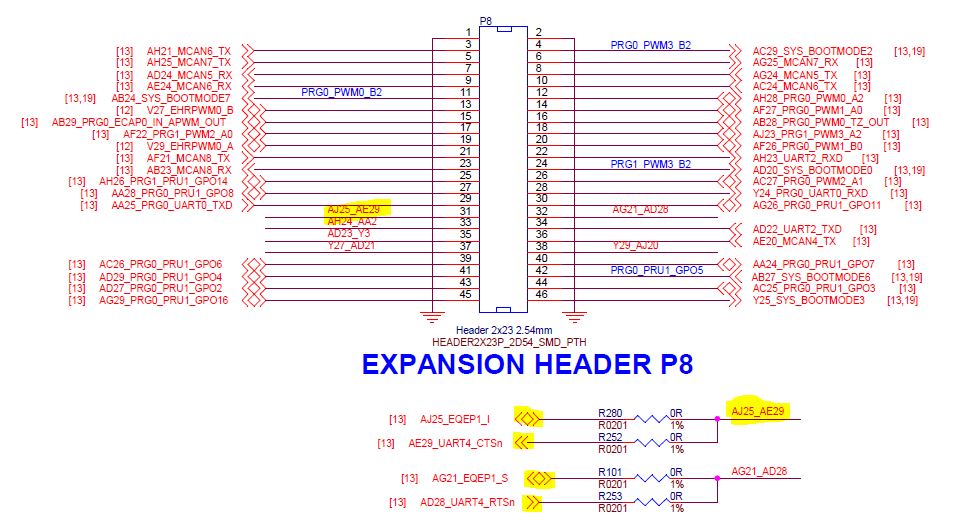
In my case, I need PRG0_PRU1_GPO0 (AE29) to be bi-directional, however the drawing shows it as an input, but shows AJ25 as bi-directional.
Right below, you can see AG21 and AD28, but in this case, AD28 is shown as an output while AG21 is a bi-directional. But again, it’s AD28 that I need because it correlates to PRG0_PRU1_GPO1.
So what’s the story with the direction arrows?
And why are pins grouped together on the same header pin? My only guess is this just to increase the chance that peripherals can be accessed on the headers but you’ll have to be careful not to activate both at the same time.