I can see that it’s MSSIO B3 13, MSS_Configuration.cfg has that mapped to GPIO_0_13, then BVF_RISCV_SUBSYSTEM.tcl maps that to USER_BUTTON which is also exposed in BVF_GATEWARE.tcl.
I reference it as an input in my Verilog, but it does not seem to do anything, although it compiles fine.
I also tried connecting it in my ADD_CAPE.tcl using sd_connect_pins -sd_name ${sd_name} -pin_names {"BVF_RISCV_SUBSYSTEM:USER_BUTTON" "USER_BUTTON"
But that just failed to compile, presumably because it’s already connected?
Any ideas would be great! I’m 1-week new to Verilog, so smashing rocks together over here haha. Cheers
It is not possible to route the user button to the FPGA. The user button is connected to a PolarFire SoC microprocessor subsystem (MSS) GPIO controller dedicated IO.
Hmm… that diagram needs to be updated. The user button is connected to input 13 of MSS GPIO controller 0. The I/Os from MSS GPIO controller 0 cannot be connected to the FPGA fabric. Only MSS GPIO controller 2 I/Os are connected to the FPGA fabric.
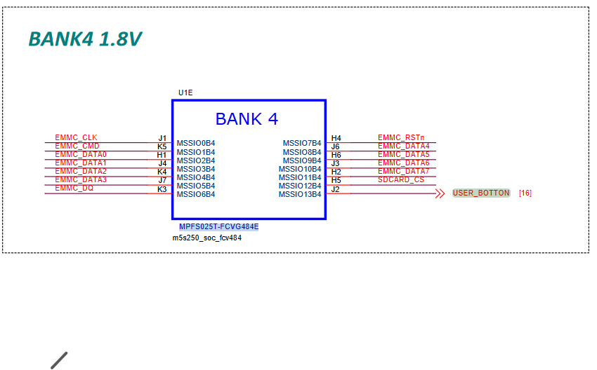
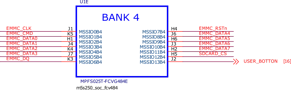
So I thought it would have been accessible. It says GPIO_0_13 there, and https://docs.beagleboard.org/latest/_images/soc-bank4.webp shows it connected to IO13 but of that bank4, so I thought perhaps it would be accessible via that somehow? Eg the PF_SOC_MSS instance being some interconnet-?
-shrugs-
I feel like I got close by changing some pin mappings, but ended up with error
Error: PAD pin ‘BVF_RISCV_SUBSYSTEM:USER_BUTTON’ is not allowed to connect to non-top level port.
Which I figure was due to me connecting that to CAPE, and then in my module instance inside cape trying to access it, instead of connecting it directly to my module.
The TCL script entries are a way to give a name to that pin/pad in the gateware.
The error message you were getting is actually meaningful. It is saying that there is something special about the USER_BUTTON signal in the gateware design. That it has to be directly connected to a pin on the chip.
The graphical representation of the gateware in Libero gives that hint by coloring the signal lines differently. Orange colored signals are top level signals connected to a pad/pin of the device. The black lines are FPGA fabric signals.
Hi @Vauban,
I think I’m starting to understand the PolarFire SoC naming convention. On the schematic, pins with the MSSIO prefix go directly to the MSS processors, and are not accessible to the FPGA fabric gateware. So all the pins in the following snippet are dedicated to the MSS? Is this correct? Thanks.
So how come the USER_BUTTON is in the TCL files then if it’s not accessible from the FPGA? From what I would imagine, if the schematic is wrong and it’s wired to MSS not FPGA (which matches the naming convention in the TCL), would it not be accessible via FIC?
Eg it looks like the RESET button - which I have tested and can use as a user button in my FPGA (ignoring that the MSS completely resets when I do) - is accessible to the FPGA via CLOCKS_AND_RESETS:FIC_3_FABRIC_RESET_N.
I apologise if I am way off the mark, and I greatly appreciate your time and input on this. Trying to learn how it’s all interconnected when some of the datasheets appear incorrect is a tad challenging haha.
From that webpage you can also get the free silver license after registration.
A good first introduction on Libero, just in case you are not familiar with it, is here:

