Using ADXL345 accelerometer and device tree settings.

Hello, I am currently trying to use Seeed Stdio’s Axis Digital Accelerometer(https://goo.gl/trxNGK) which uses ADXL345 accelerometer. And I am writing this mail to get some advices for writing a device tree node.

All of the examples I found on the Internet are to write ‘user level’ application that controls this chip via I2C bus.

But instead of controlling it in the user level, I want to use the Linux Kernel’s ADXL34x device driver (https://goo.gl/wxGzDC) because the purpose of this project is to get an experience of using existing device driver.

So firstly, I am investing this driver’s init and probe functions to add an device tree node to describe this device.

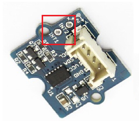
But the problem is that whereas user level examples doesn’t use interrupts, I need to describe interrupt pins according to folliwing articles:

5A0363D5550644C0A9A587BBE9555553.jpg

So my questions are:
What is the purpose of the interrupt pins? I couldn’t understand exactly when I read the datasheet.

I did work with grove module but it was almost 2 years ago so I am
trying to remember. From what I recall, the Linux kernel driver
expects there to be an interrupt setup for this device.

The other odd this about this device is that it is it uses a driver in
"drivers/input/misc". I think it is because IIO did not exist at the
time?

Should I describe interrupt pins for this device?

I think I used mini-hooks to connect INT1 or INT2 to the BeagleBone
header and then defined the interrupt pin in an overlay.

I'll see what I can dig up... but if someone else has more recent
experience that would be great.

thanks,
drew