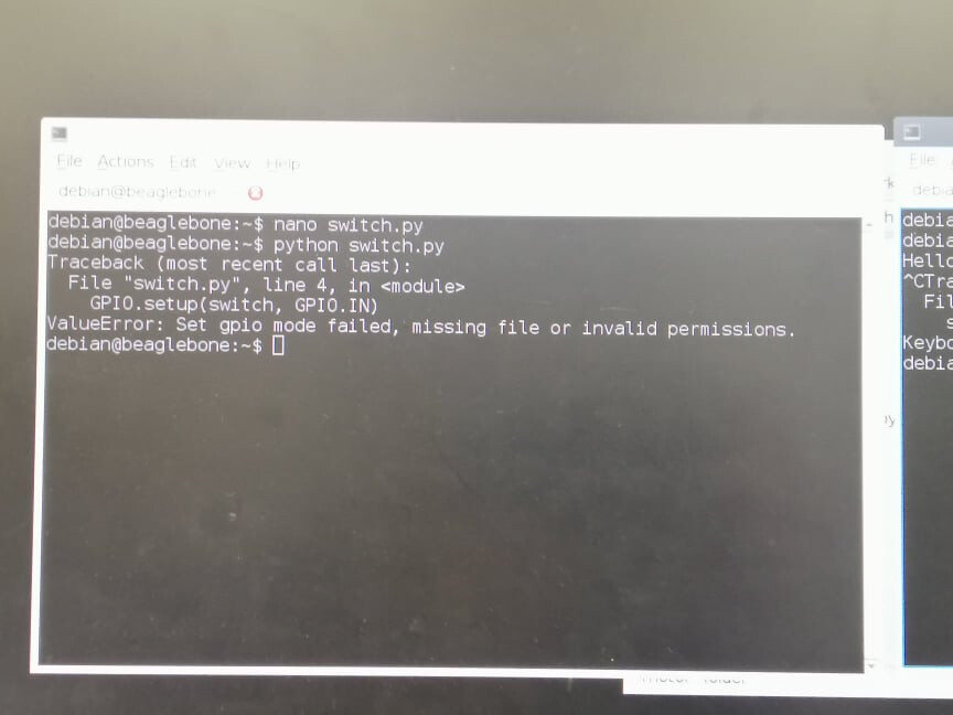
Hi, I’ve been trying to set up a GPIO pin on the BeagleBone AI as an input but keep getting this error. I’ve confirmed that I am using the correct GPIO pin, it works as an output, but just can’t get it to work for an input.
Does anyone have any suggestions about what could help fix this, or a different approach to receiving an input from the GPIO pins?
The code I’m using is as follows:
import Adafruit_BBIO.GPIO as GPIO
switch = “P9_31”
GPIO.setup(switch, GPIO.IN)
exit_loop = 1
while exit_loop:
if GPIO.input(switch):
print(“Switch On”)
exit_loop = 0
GPIO.cleanup()
I tried using Adafruit_Blinka but it just results in an endless list of errors when trying to install/use the library. I know there are differences between the pins for the Black (which adafruit_BBIO is designed for) and the AI, but I’ve found GPIO pins using them as outputs.
If you were able to get it the libraries to work on a BBAI pin as an output, that would be interesting. But, one thing you could try is to map a BB Black GPIO Pin value to a BB AI GPIO pin and see if you can fake out the libs. No guarantee that the pin is mapped to a generic GPIO pin or being used for something else though. You would have to see the references provided previously for clarification.
For the BBAI, P9_15 would have to be enabled in the .dts for the kernel that is running.
On the BBAI, P9_31 is mapped to gpio5_10 (gpio138) and shown as gpio110 “SPI1_SCLK” for the BBB. I did not find a gpio110 for the BBAI in the spreadsheet.
Yes, the BB pin P8_39 is the BBAI GPIO 76 (P9_15), that works perfectly fine on the AI as an output pin, but I’ve had issues with setting it up as an input pin.
I’m aware that the Adafruit_BBIO library isn’t very compatible with the AI, but I thought once I worked out how the pins match, I could get it to work. But unfortuantely I am only able to output signals using GPIO.setup(“P8_39”, GPIO.OUT)
Thanks for your help but I think I’ll just have to go with my alternative of using an arduinos serial output to send an input to my AI board.
I might give this a go/investigation, thanks
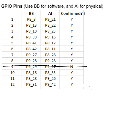
For reference, these are the pins I found work as outputs on the BBAI using the Adafruit_BBIO library. You use the BB pin for the software pin setup, but physically connect at the AI pin location:
You have to look at how the pin is defined in the .dts that is running. If it is not set to INPUT, then you would have to set it as such and rebuild the dtb.
I did this for P8.22 and P8.23:
Ex:
DRA7XX_CORE_IOPAD(0x3798, PIN_INPUT | MUX_MODE14) /* AD6: P8.22: mmc3_dat5.off /
DRA7XX_CORE_IOPAD(0x3794, PIN_OUTPUT | MUX_MODE14) / AC8: P8.23: mmc3_dat4.off */
Then you can can create your own Python script, or use another language to read and write to the pins.
As far as the Adafruit_BBIO libs, it really is a matter of how they are configuring the pins. What works on the BB Black does not necessarily work on the BBAI. I configured P8.22 as an Input and can use it with other tools or just command line, but it still gets an error from the BBIO code. Until someone looks into this, it is just not going to work on the BBAI.
Hi…I included my question to this topic rather than making a new subject. I moreover need to configure gpio pins within the gadget tree (DT). I examined the over BB-P9_27-LED-00A0.dts illustration. I get it what fragment0, 1 and 2 are doing but I won’t require those parts since my DT does not incorporate P9_27_pinmux helper. If I get it accurately, fragment3 employments gpio-leds. I don’t have a ‘led’ hub in my DT.