I am currently testing to promote findings via some posts I will make.
There is the schematic of the “Hat” in question here. Is everything about that Hat only for the PWM peripherals on the BeagleY-AI?
I figured I would be using the motor drivers but it seems the PCA9685 is used for adopting a way to push PWM to the Motor Drivers and the Motor Drivers only acknowledge the PWM peripherals. I am guessing when I type that idea…
The write up on Adafruit’s website is fine but it lacks definition (I think).
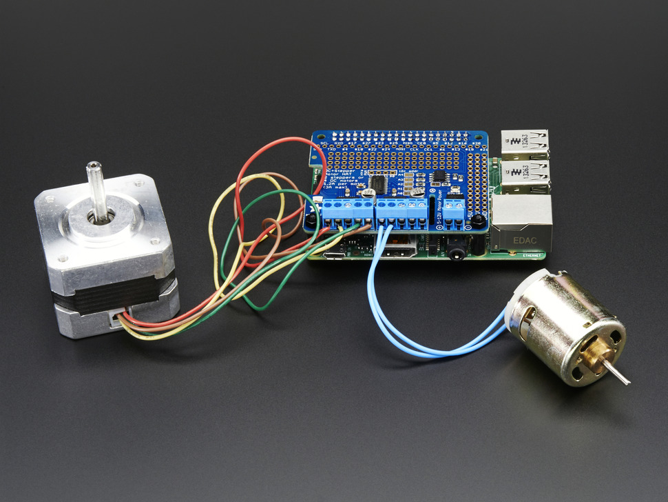
I am not even sure I understand this contraption so far, i.e. the Stepper and DC Motor Hat.
The board boots with the Hat on it. I apply a simple 9v battery and the Hat powers on for stepper usage. I am just not sure yet. Do I just use PWM peripherals from the BeagleY-AI or is there a catch somewhere I am missing?
So, from what I thought, GPIO peripheral access controls the direction while PWM peripheral access controls speed via Hz and duty_cycle.
Anyway, if you find this answer is easy to comprehend and you have time, please do reply. I will be testing some more GPIO and PWM peripheral access on the BeagleY-AI in time.
I think my source was not working and hence why I bring it up…
The issue I currently have is that the PWM peripherals are not brought out in userland.
So, I am writing a more recent image now. I will reply here for future self and others questioning me on why I am wondering about the Hat in question.
Seth
P.S. Here is an update…
Update
I put in the overlays and the PWM in userland does not get listed at /dev/bone/pwm/* via ls -l or if I traverse to the file(s) in question. The files are not located at that directory.
Is there a way to bring the PWM peripherals to the userland seeing eye here?
So, I am at a loss on what and why for now. What is going on with the PWM peripherals on the BeagleY-AI? Why are the PWM peripherals so difficult to get registered in userland?
I see people using DTSO files for arranging the DTS before compilation.
I found a nice way to compile the DTS0 via a script on the board (BeagleY-AI).
Outside of that, I see many entries in that file. The file, this DTSO, needs to be compiled to be able to utilize it. This is as far as I have been. I did read some of the files.
Is there some happy medium or am I at it alone here with PWM and the BeagleY-AI.
I know, PWM, whoopty. Oh. I found some pwmchip0 - pwmchip7 registered components within the FS.
Can I use 'em. Nope, not yet. I cannot even get gpioinfo to welcome the PWM peripherals to sight so far.
You’ll need the driver to get those pwm entries in /dev. I see one does exist; https://github.com/torvalds/linux/blob/master/drivers/pwm/pwm-pca9685.c, but I dont know whether that exists on your system. You’ll also need an overlay to configure it.
I saw a discussion on the raspberry pi forum, https://forums.raspberrypi.com/viewtopic.php?t=142566, maybe that has some usefull info on getting this to work …
So, I understand here. Get the driver, install it (however), and then find out how to create an overlay for the pins in question for the DTC and BeagleY-AI.
I suggest these steps for getting the PCA9685 working at kernel:
setting up an device tree overlay which enables the PCA9685 device from Linux kernel perspective. The driver should be already on-board.
Once kernel loads it, enable PWM channels, and configure them with period and duty cycle.
The device tree overlay source should look like below. The I2C address here used is “0x40” - you’d have to adapt the pca9685@40 and the reg = <0x40> if your board uses a different address. For figuring out the I2C devices connected to the BeagleY-AI there should be instructions available.
Add it to the /boot/firmware/extlinux/extlinux.conf, at the bottom using fdtoverlays ....
Once the kernel boots up with it you should find the device somewhere under /sys/bus/i2c/devices/... or /sys/class/pwm/pwmchipX/.... For example:
$ cat /sys/class/pwm/pwmchip0/device/name
pca9685
Then you have to set up the pwm channels of this chip. Servos are using as far as I know always a fixed period of 20ms. The duty length is expected at 1ms…2ms with “0” at 1.5ms. This script could help:
#!/bin/bash
#
# servo_setup.sh - run as root!
#
PWMCHIP=/sys/class/pwm/pwmchip0
CHANNELS="0 1"

# setup period + duty cycle on both pwm0 and pwm1
for id in $CHANNELS
do
    if [ ! -d $PWMCHIP/pwm$id ]; then
        # create pwm<id>
        echo $id > $PWMCHIP/export
        sleep 0.5
    fi
    echo 20000000 > $PWMCHIP/pwm$id/period
    echo 1500000 > $PWMCHIP/pwm$id/duty_cycle
done
Then you can control the pwm by echoing to the duty_cyle:
# probably as user "root"...
echo 1700000 > /sys/class/pwm/pwmchip0/pwm0/duty_cycle
# again "0"-position:
echo 1500000 > /sys/class/pwm/pwmchip0/pwm0/duty_cycle
Thank you. I was off (as usual). I will attempt this idea too. I will report back once things are either configured correctly or if I have another question.
regarding your example: as mentioned, for a Servo Motor you must use a PWM period of 20ms or 50Hz. And the duty cycle must be in the range 1…2ms. For the /sys/.../pwmX interface this means:
On my board it’s 0x40 it depends on how the address pins of the PCA9685 device on your board are configured. Once the kernel takes control of the PCA9685 (-> the overlay gets loaded and the driver gets starte), the device appears as UU in the output of i2cdetect. On my system it looks like:
And no, the “pwmchipX” number is not related with the I2C bus number used by i2cdetect. I’d think I2C bus 1 is the one which is exposed on the BeagleY-AI GPIO pins. So your PCA9685 most likely should appear on I2C bus 1.
I got some better results. 0x40 quits the running boot when applied.
For whatever reason, that is what happens. Then, one needs to hold the boot/power button down to turn off the board, take the USB C out of the dev. desktop, and then reapply USB C power for networking to get it booting regularly again.
Would I need a separate DTS file for using a stepper or is this DTS file an okay start for using a stepper motor?
I don’t know your setup, but from what you tell I can imagine, that your HAT powers the motor(s) exactly at that time when setting up the PCA9685. The boot failing at that time indicates that the motor(s) draw too much power so that your BeagleY-AI does no more get enough and stops booting.
The overlay is only for the PCA9685. I would try booting without the motors connected and see if the PCA9685 gets detected.
After that check your power supply. Maybe the motors need a separate power source.
Yeah for some background - I wrote that bit of docs when we were trying to prototype the Drink dress last year so it’s all I2C userspace Python just for simplicity. I hadn’t looked at proper kernel implementation.
How would I test to see if my current kernel supports these picks from menuconfig?
Device Drivers --->
   <*> Pulse Width Modulation(PWM) Support --->
      <*> eHRPWM PWM support
I seem to have no idea how to test. But…in some light here, the PWM in /sys/class/pwm/ has pwmchip0 - 7 with some not being available…
And other sections of the beagleboard.org kernel I am using seem to have them available for usage but not in userland applications.
Is there a specific way to test in the ssh terminal application for PWM and if it is indeed ready to be used or would I need to write a kernel with the Device Drivers myself?
Seth
Update
A and Okay here, I seem to have one channel per chip only. As I read the docs more from TI, the two channels are supposed to be brought out to userland for use cases.
What do I need to do, if anything, to bring out the two channels from each chip? Scratch that question…
It seems there are exactly two usable double channels per chip for specific chips only. I got it now… Things are a bit buggy for me on kernel:
6.6.58-ti-arm64-r24
With this image and that kernel, I am getting slips in timing when typing in the ssh terminal: