CAN Overlay missing for BeagleBone AI-64

Hello Devs,

I am trying to integrate CAN on BeagleBone AI-64 and can see there is no CAN overlay file for version 5.10.153. in DeviceTreeOverlay

I have tried with v4.19.x but, now I am not able to connect with the board (via SSH or browser). Looks, like the boot is messed up someway.

Please help with this situation.

Thank you

hi @ss13ms110

If you can’t get into the board with a serial connection you will probably need to reflash the eMMC.

When playing around with devicetree overlays, or the kernel in general it is better to boot from an SD card anyway, as it is much easier to fix things if you break the boot.

Which interface and pins are you trying to use ?

Some if the CAN pins are on dual use pins so you will need to make sure the alternative function is set as an input.

So taking CAN0 RX on P9.19, TX on P9.20 you will need something like this.

This is on 5.10.153-ti-arm64-r84
BeagleBoard.org Debian Bullseye Minimal Image 2023-01-02

/dts-v1/;
/plugin/;

#include <dt-bindings/pinctrl/k3.h>

&main_pmx0 {
   
   main_mcan0_pins_default:main_mcan0-pins-default {
      pinctrl-single,pins = <
      J721E_IOPAD(0x20C, PIN_OUTPUT, 0) /* W6: MCAN0_TX W6_AE25 */
      J721E_IOPAD(0x138, PIN_INPUT, 7) /* AE25: PRG0_PRU1_GPO14 W6_AE25 */
      J721E_IOPAD(0x208, PIN_INPUT, 0) /* W5: MCAN0_RX W5_AF29 */
      J721E_IOPAD(0x13C, PIN_INPUT, 7) /* AF29: PRG0_PRU1_GPO15 W5_AF29 */
      >;
   };
};

&bone_led_P8_45 {
   label = "CAN0";
   status = "okay";
};


&main_mcan0 {
   status = "okay";
   pinctrl-names = "default";
   pinctrl-0 = <&main_mcan0_pins_default >;
};

I am controlling the transceiver enable pin separately . I think there are options to add a GPIO pin to the CAN, but I went with using an LED pin as these are setup already for every header pin, they just need to be enabled, which is what the bone_led_P8_45 section does. Depending on how your transceiver is setup you will need to change this.

In the above dts the enable pin is controlled by writing a 1 or 0 to
/sys/class/leds/CAN0/brightness

2 Likes

Hello @benedict.hewson

Thank you for the reply. I am able to setup CAN overlay. Steps I have followed:

  1. Git clone BeagleBoard Device Trees

$ git clone https://git.beagleboard.org/beagleboard/BeagleBoard-DeviceTrees.git

$ cd BeagleBoard-DeviceTrees

  1. Edit k3-j721e-beagleboneai64-bone-buses.dtsi in src/arm64 and add the following lines at the end

bone_can_0: &mcu_mcan0 {
                 pinctrl-names = "default";
                 pinctrl-0 = <
                              &P9_19_can_pin /* mcan0_rxd */
                              &P9_20_can_pin /* mcan0_txd */
                             >;
                 symlink = "bone/can/1";
                 status = "disabled";
};

  1. Create new CAN0 overlay file BONE-CAN0.dts with the following content in src/arm64/overlays/
/*
* Copyright (C) 2022 BeagleBoard.org - https://beagleboard.org/
*
* https://elinux.org/Beagleboard:BeagleBone_cape_interface_spec#CAN
*/

/dts-v1/;
/plugin/;

/*
* Helper to show loaded overlays under: /proc/device-tree/chosen/overlays/
*/

&{/chosen} {
        overlays {
                  BONE-CAN0.kernel = __TIMESTAMP__;
                 };
           };

&bone_can_0 {
        status = "okay";
            };

  1. Compile and install from parent directory BeagleBoard-DeviceTrees

$ make
$ sudo make install

  1. Reboot

$ sudo reboot

  1. Test if CAN interfae is loaded

$ sudo beagle-version | grep UBOOT

UBOOT: Booted Device-Tree:[k3-j721e-beagleboneai64.dts]
UBOOT: Loaded Overlay:[BONE-CAN0.kernel]

  1. Check for CAN interface in ip link

$ ip link

can0: <NOARP,ECHO> mtu 16 qdisc noop state DOWN mode DEFAULT group default qlen 10
    link/can

It shows can0 is DOWN. To make it available, run:


$ sudo ip link set can0 up type can bitrate 1000000
$ ip link

can0: <NOARP,UP,LOWER_UP,ECHO> mtu 16 qdisc pfifo_fast state UP mode DEFAULT group default qlen 10
    link/can

  1. Increase txqueulen

$ sudo ifconfig can0 txqueuelen 100

After following these steps I am able to send TX messges from terminal but candump shows no output. When I do

$ ip -det link show can0
3: can0: <NOARP,UP,LOWER_UP,ECHO> mtu 16 qdisc pfifo_fast state UP mode DEFAULT group default qlen 1000
    link/can  promiscuity 0 minmtu 0 maxmtu 0 
    can state ERROR-ACTIVE (berr-counter tx 0 rx 0) restart-ms 0 
	  bitrate 1000000 sample-point 0.750 
	  tq 12 prop-seg 29 phase-seg1 30 phase-seg2 20 sjw 1
	  m_can: tseg1 2..256 tseg2 2..128 sjw 1..128 brp 1..512 brp-inc 1
	  m_can: dtseg1 1..32 dtseg2 1..16 dsjw 1..16 dbrp 1..32 dbrp-inc 1
	  clock 80000000 numtxqueues 1 numrxqueues 1 gso_max_size 65536 gso_max_segs 65535

It shows can state ERROR-ACTIVE

What could be the reason? I hope you help.

Thank you

Best
Shubham

1 Like

I would advise keeping all of the can parts in its own DTS file. That way if you do an update on your system and rheain DTS file gets changed your can will still work and obviously keep a.copy…off the BB in case you need to reflash it.

Have you got another device on the can bus to ack the message ?

Is the can bus properly terminated ?

Have you.got access to a scope, if so check you have activity on the bus side of the transceiver

1 Like

Hi @benedict.hewson

Thank you for the response.

I will separate the CAN dts in a separate file leaving the original file as it is.

Have you got another device on the can bus to ack the message ?

Yes, this is my CAN setup

Is the can bus properly terminated ?

I am not sure how to check this.

Have you.got access to a scope, if so check you have activity on the bus side of the transceiver

I do not have an oscilloscope, I will try to get my hands on one or may be a multimeter if that works.

I am completely new to electronics and hardware (single board computers). I apologize in advance if I might ask something stupid.

This is my terminal output (left-terminal: left BB-AI64 and right-terminal: right BB-AI64 from image above)

When I do cansend can0 123#abcdef nothing happens.

Thank you

Best
Shubham

EDIT:
When I look in /proc/net/can

debian@BeagleBone:/proc/net/can$ ls
rcvlist_all  rcvlist_err  rcvlist_inv  reset_stats
rcvlist_eff  rcvlist_fil  rcvlist_sff  stats
debian@BeagleBone:/proc/net/can$ more stats 

       52 transmitted frames (TXF)
        0 received frames (RXF)
        0 matched frames (RXMF)

        0 % total match ratio (RXMR)
        0 frames/s total tx rate (TXR)
        0 frames/s total rx rate (RXR)

        0 % current match ratio (CRXMR)
        0 frames/s current tx rate (CTXR)
        0 frames/s current rx rate (CRXR)

        0 % max match ratio (MRXMR)
        5 frames/s max tx rate (MTXR)
        0 frames/s max rx rate (MRXR)

        0 current receive list entries (CRCV)
        1 maximum receive list entries (MRCV)
debian@BeagleBone:/proc/net/can$

Which means it is transmitting messages (left BB-AI64). But, on right BB-AI64 there is just 1 transmitted message (as expected) and no received messages.

debian@BeagleBone:/proc/net/can$ ls
rcvlist_all  rcvlist_err  rcvlist_inv  reset_stats
rcvlist_eff  rcvlist_fil  rcvlist_sff  stats
debian@BeagleBone:/proc/net/can$ cat stats 

        1 transmitted frames (TXF)
        0 received frames (RXF)
        0 matched frames (RXMF)

        0 % total match ratio (RXMR)
        0 frames/s total tx rate (TXR)
        0 frames/s total rx rate (RXR)

        0 % current match ratio (CRXMR)
        0 frames/s current tx rate (CTXR)
        0 frames/s current rx rate (CRXR)

        0 % max match ratio (MRXMR)
        1 frames/s max tx rate (MTXR)
        0 frames/s max rx rate (MRXR)

        1 current receive list entries (CRCV)
        1 maximum receive list entries (MRCV)
debian@BeagleBone:/proc/net/can$

Thank you

1 Like

Both ends of the cable should be terminated with a 120 Ohm resistor. If you have more than two participants on the bus, then all of them must have no resistance in between. With two connected 120 Ohm resistors, you must be able to measure 60 Ohm. It’s been 50 years since I learned this, add the reciprocals of the resistors and make the reciprocal again, ohms law I think.

Yes ohms law. :slight_smile:
Here are two photos of how I did it.


R2 is a 120 Ohm resistor and can be switched with J1.

Here I have measured the 60 Ohm.

With your CAN bus transceiver breakout, the resistor does not seem to be switchable, so if you have more than two bus participants, you would have to desolder the resistors on the inner participants. Terminating resistors may only be used for bus termination at the ends.

What transceivers are you using ?
They probably do not have terminating resistors or if they do there should be a jumper to disable it.

Are they 3v compatible ?

Also make sure both boards have a common ground

To check for termination resistors just use a DVM on ohms and measure across can high and can low with nothing powered. It should measure 60ohms give or take.

Hello @benedict.hewson and @SunWukong

What transceivers are you using ?
They probably do not have terminating resistors or if they do there should be a jumper to disable it.

I am using these transreceiver. They look like cheap copy of waveshare transreceivers shared by @SunWukong. Someone in the discussion under the product asked if the CANL and CANH are terminated with 120 ohm resistor and the answer was yes. Here is a picture of the same.

There seems to be 2 resistors once 103 ohm connected to ground and another 121 ohm sorted between CANL and CANH.

Are they 3v compatible ?

They are 3.3 v compatible

Also make sure both boards have a common ground

Tried with common ground, doesn’t work.

check for termination resistors just use a DVM on ohms and measure across can high and can low with nothing powered. It should measure 60ohms give or take.

Will try this as soon as the multimeter will be delivered.

I have a question. How can I check if correct pins are active (p9.19 and p9.20)? is there any list which can be seen for activated pins?

Also, unknowingly I sorted the CANL and CANH, I guess the transreceiver is not useful anymore?

Thank you

Best
Shubham

Can transceivers are pretty robust and shorting can high and can low will probably be ok. They should also survive being shorted to ground or supply volts.

Can’t really tell from the photo,but I expect the 2 pins need to have a jumper to add the terminating resistor

If you don’t have them fitted it isn’t terminated.

The 103 (10k) resistor will either be a pull up or pull down to enable the transceiver. Will depend on the chip used.

Hi @benedict.hewson

Here is the schematic of the board.
Screenshot from 2023-03-19 13-54-55

and the chip used is: SN65HVD230

They don’t show the 2 header pins on there.
Almost certainly the pins are there to enable/disable the 120 ohm resistor. Most of the time you won’t want the termination resistor especially when connecting to an existing can network

I guess the two pin jumper is a second option to install the CANH and CANL lines and is in parallel to the terminal block connector. I have seen this many times before. I have also used this jumper on my modules to connect my test leads in parallel. Please take a closer look at my foto CAN-Bus 2.

Yes those are in parallel with CANH and CANL. There is no jumper to enable/disable the resistor. Looks like the resistor is permanently connected to CANH and CANL. I am waiting the multimeter to be delivered. I have also ordered the original Waveshare CAN Transceiver. Let’s see how it goes.

Thank for the help @benedict.hewson and @SunWukong

I will update this thread as soon I will have some success.

1 Like

It is a bit of a dumb design if you can’t isolate the termination resistor.

Anyway once you get a DVM it should be obvious.

If you take the DTS snippet I posted above and createan overlay file it should work once loaded. The pin muxing works fine for me.

Hello @benedict.hewson and @SunWukong

I got my multimeter and new (original) waveshare CAN transceivers delivered.

This is the multimeter reading, 59.3 ohm. Which means there are terminating resistors.

Still I am facing the same issue. CAN message from one BBAI-64 cansend can0 123#ABCDEF is not received on other BBAI-64 candump can0

Thank you

1 Like

Ok, then your problem is either going to be pin muxing, or the CAN peripheral itself is not set correclty.

I always set the bit rate before bringing up the interface. I have a small bash script to make my life easier.

#!/bin/bash

sudo ip link set down $1
sudo ip link set $1 type can bitrate $2
sudo ip link set up $1

then for example just do setcan can0 250000

Thanks for the prompt reply.

I was also setting the bitrate everytime making can0 up.

I didn’t try your dts file. I am a bit confused about using your dts snippet. Please correct me where I go wrong.

  1. Create a separate dts file (lets say BONE-CAN0.dts) copy paste that snippet.
    Doubt: This snippet only shows overlay for one pin (P8_45), what about the other pin?

  2. Compile the dts file to dtbo.

  3. Copy it to /boot/overlays

  4. Edit /boot/firmware/extlinux/extlinux.conf

  5. reboot

Is that all I have to do? Or am I missing something?

I guess if this works, this should solve the issue.

Thank you

Best
Shubham

Ok guide to writing the overlay.

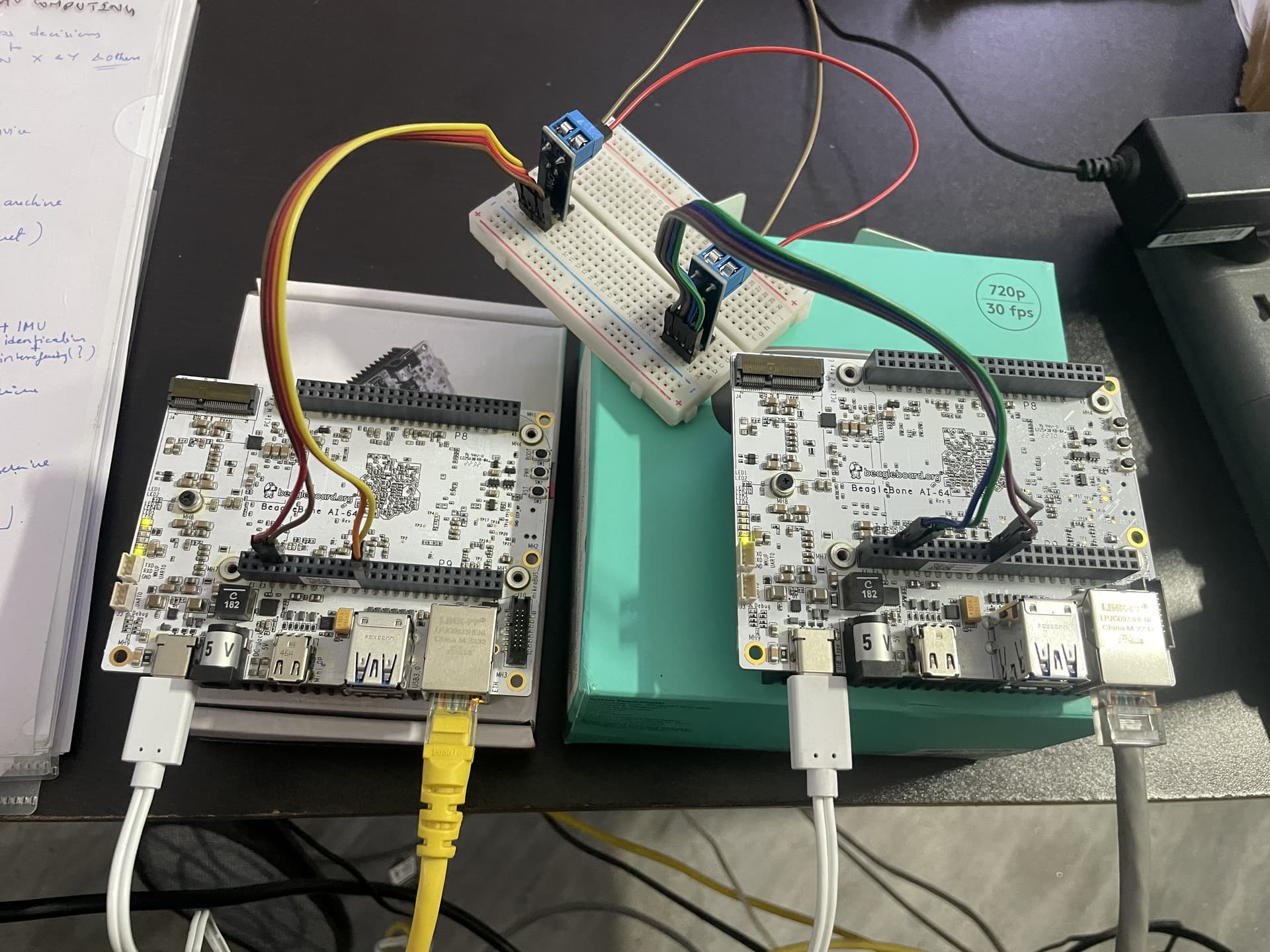
This is on the BBAI-64.

By the way if you haven’t updated the default image on the board I would do so at some point. Obviously reflashing will overwrite any changes you do.

If you check the file system, you should find an /opt/source directory.
Depending on the kernel you are booting there should be a dtb-x.xx directory to match your kernel.

So mine is dtb-5.10-ti, yours may be different.

Inside /opt/source/dtb-5.10-ti/src/arm64/overlays/
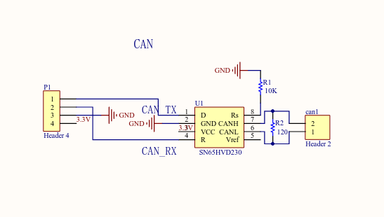
create your overlay file. e.g BONE-CAN0.dts

edit this to add

/dts-v1/;
/plugin/;

#include <dt-bindings/pinctrl/k3.h>

&main_pmx0 {
   
   main_mcan0_pins_default:main_mcan0-pins-default {
      pinctrl-single,pins = <
      J721E_IOPAD(0x20C, PIN_OUTPUT, 0) /* W6: MCAN0_TX W6_AE25 */
      J721E_IOPAD(0x138, PIN_INPUT, 7) /* AE25: PRG0_PRU1_GPO14 W6_AE25 */
      J721E_IOPAD(0x208, PIN_INPUT, 0) /* W5: MCAN0_RX W5_AF29 */
      J721E_IOPAD(0x13C, PIN_INPUT, 7) /* AF29: PRG0_PRU1_GPO15 W5_AF29 */
      >;
   };
};

&main_mcan0 {
   status = "okay";
   pinctrl-names = "default";
   pinctrl-0 = <&main_mcan0_pins_default >;
};

edit the Makefile in that directory to add you new dts file

dtbo-$(CONFIG_ARCH_K3) += \
	BONE-CAN0.dtbo \
	BBAI64-CSI1-imx219.dtbo \

from /opt/source/dtb-5.10-ti/
do
make
and then
make install

Assuming there are no errors that should create the dtbo file and then copy it to
/boot/dtbs/5.10.153-ti-arm64-r84/ti/overlays/

Double check to make sure it is there.

Then edit /boot/firmware/extlinux/extlinux.conf

Either add or edit the fdtoverlays line

fdtoverlays /overlays/BONE-CAN0.dtbo

save and reboot.

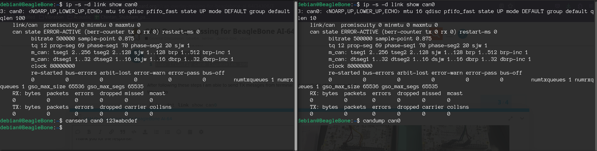
Once booted you can then do

ls /proc/device-tree/chosen/overlays/

And you should see BONE-CAN0 assuming everything has worked.

Then proceed with configuring the CAN interface and testing.

Hi @benedict.hewson

The can is UP like last time.

But the problem persist. I think something is wrong with the CAN peripheral itself.

Do you have any suggestion how can I troubleshoot the connections using MultiMeter. I measured the resistance it is 60 ohms.

Here is my schematics, If this is correct then the last thing remaining is to check connections if they are tight enough or not (although that has already been checked).

Please have a look.

Thank you

Best
Shubham

Connect gnd from BB1 to BB2, beyond that you may need a scope to check signals.

1 Like