CAN setup in BeagleBone AI-64

Hello Devs,

I am creating this topic for people out there looking for how to setup CAN in BeagleBone AI-64. I had a long discussion with @benedict.hewson and @SunWukong (here) and they helped me to go through this. Same scheme can be followed to integrate other overlays in BB AI-64.

Image used: bbai64-debian-11.6-xfce-edgeai-arm64-2023-01-02-10gb.img.xz

Steps to setup DTS overlay for CAN in BeagleBone AI-64

Note: Apply updates from here before proceeding

  1. Goto /opt/source/dtb-5.10-ti
$ cd /opt/source/dtb-5.10-ti/
  1. Create new CAN0 overlay file BONE-CAN0.dts in src/arm64/overlays/
/dts-v1/;
/plugin/;

/*
 * Helper to show loaded overlays under: /proc/device-tree/chosen/overlays/
 */
&{/chosen} {
	overlays {
		BONE-CAN0.kernel = __TIMESTAMP__;
	};
};

/* Change pinmux*/

&main_mcan0 {
	pinctrl-names = "default";
	pinctrl-0 = <
		&P9_19_can_pin /* mcan0_rxd */
		&P9_20_can_pin /* mcan0_txd */
	>;
	symlink = "bone/can/1";
	status = "okay";
};

  1. Compile and install from parent directory dtb-5.10-ti.
$ make 
$ sudo make install
  1. After compilation edit /boot/firmware/extlinux/extlinux.conf by replacing
    #fdtoverlays /overlays/<file>.dtbo
    with
    fdtoverlays /overlays/BONE-CAN0.dtbo
$ sudo vi /boot/firmware/extlinux/extlinux.conf
  1. Reboot
$ sudo reboot
  1. Test if CAN interface is loaded
$ sudo beagle-version | grep UBOOT

UBOOT: Booted Device-Tree:[k3-j721e-beagleboneai64.dts]
UBOOT: Loaded Overlay:[BONE-CAN0.kernel]
  1. Check for CAN interface in ip link
$ ip link

can0: <NOARP,ECHO> mtu 16 qdisc noop state DOWN mode DEFAULT group default qlen 10
    link/can

It shows can0 is DOWN. To make it available run:

$ sudo ip link set can0 up type can bitrate 1000000
$ ip link 

can0: <NOARP,UP,LOWER_UP,ECHO> mtu 16 qdisc pfifo_fast state UP mode DEFAULT group default qlen 10
    link/can
  1. Increase txqueulen
$ sudo ifconfig can0 txqueuelen 100
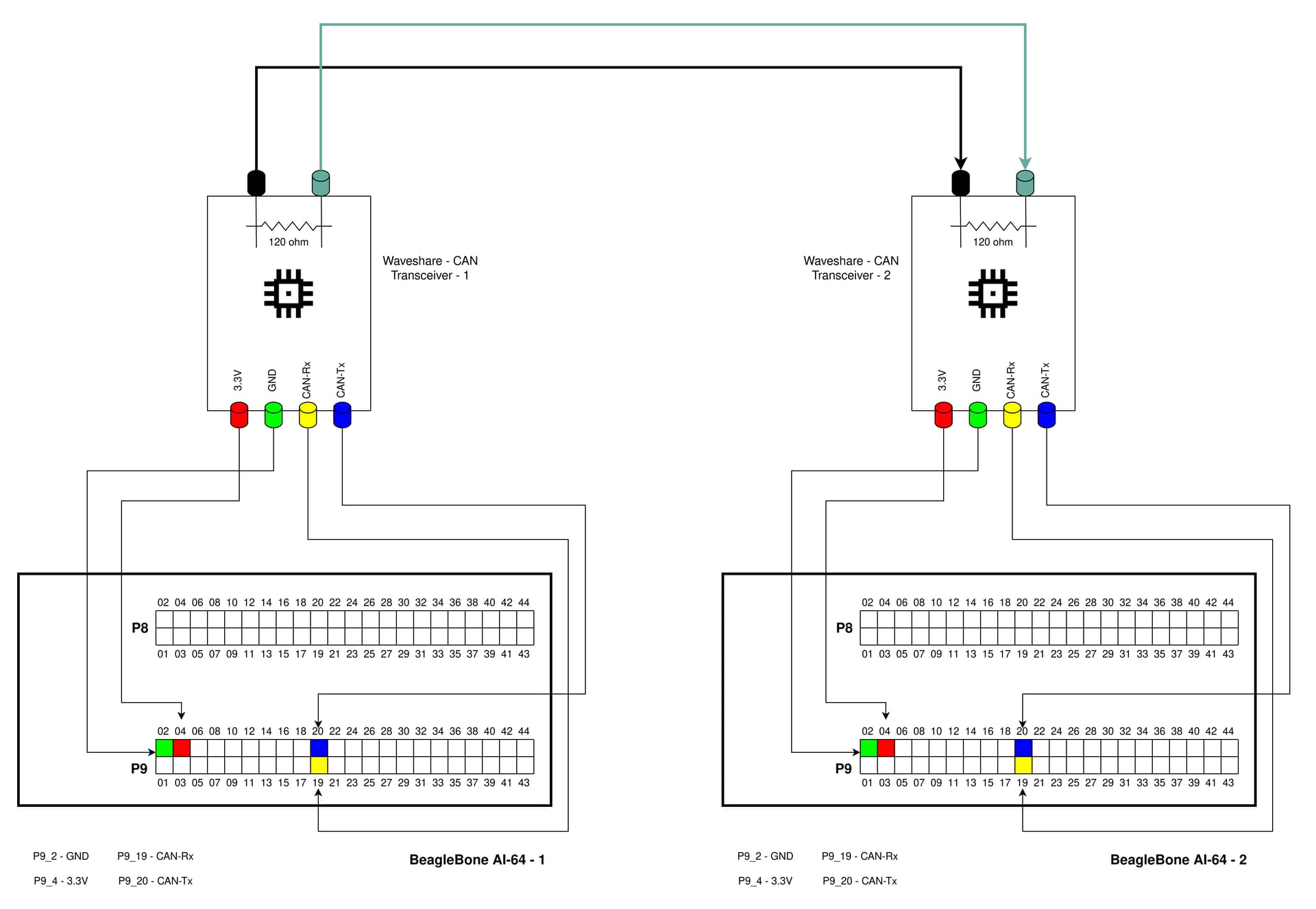
  1. Representative diagram showing how to connect CAN transceivers with two BeagleBone AI-64.
    Note: In order for CAN to work, you need atleast 2 nodes

  1. Use cansend and candump to send and receive CAN signals from one BBAI-64 to other

BB AI-64 2

candump can0

BB AI-64 1

cansend can0 435#4D.99.73.21.79.89.D4.73

I hope this helps

Thank you

Best
Shubham

fdtoverlays /overlays/BONE-CAN0.dtbo

Thanks @chkvsk

I have made the correction.

Sorry for the simple question. I’m using capes with CAN routed as can1 to the pins P9.24 and P9.26. Tried to complete setup with creating BONE-CAN1.dts with no success. What need to be changed in setup process to setup can1?

Thanks

P9.24 & P9.26 is connected to main_mcan4 so you will need in your overlay


&main_pmx0 {
   main_mcan4_pins_default:main_mcan4-pins-default {
      pinctrl-single,pins = <
      J721E_IOPAD(0x30, PIN_OUTPUT, 6)  /* AF24: PRG1_PRU0_GPO11 Y1_AF24 */
      J721E_IOPAD(0x1DC, PIN_INPUT, 7) /* Y1: SPI1_CLK Y1_AF24 */
      
      J721E_IOPAD(0x34, PIN_INPUT, 6)  /* AJ24: PRG1_PRU0_GPO12 Y5_AJ24 */
      J721E_IOPAD(0x1E0, PIN_INPUT, 7) /* Y5: SPI1_D0 Y5_AJ24 */
      
      >;
   };

};

&main_mcan4 {
	status = "okay";
	pinctrl-names = "default";
	pinctrl-0 = <&main_mcan4_pins_default >;
};

They will get enumerated as can0 and can1, however I am not 100% sure if they will always get enumerated in the same order, or that mcan4 will be can1.

You can add a udev rule to set the name for the interface. I am doing this for my 6 CAN channels as I have labelled them on the pcb, with the hardware interface.

So basically you can create a udev rule like this, which sets the name to the actual hardware peripheral.

put the file in /etc/udev/rules.d/

#11-can.rules

KERNELS=="2701000.can", ACTION=="add", NAME="CAN0"
KERNELS=="2741000.can", ACTION=="add", NAME="CAN4"
KERNELS=="2751000.can", ACTION=="add", NAME="CAN5"
KERNELS=="2761000.can", ACTION=="add", NAME="CAN6"
KERNELS=="2771000.can", ACTION=="add", NAME="CAN7"
KERNELS=="2781000.can", ACTION=="add", NAME="CAN8"

This sets my can interface names to the above, rather than can0-can5 as that is confusing for me. Put anything you like for the name.

Thank you, It was even easier than I thought:

3: can0: <NOARP,UP,LOWER_UP,ECHO> mtu 16 qdisc pfifo_fast state UP group default qlen 10
link/can
4: can1: <NOARP,UP,LOWER_UP,ECHO> mtu 16 qdisc pfifo_fast state UP group default qlen 10
link/can

I created another BONE-CAN4.dts

/dts-v1/;
/plugin/;

/*
 * Helper to show loaded overlays under: /proc/device-tree/chosen/overlays/
 */
&{/chosen} {
    overlays {
		BONE-CAN4.kernel = __TIMESTAMP__;
    };
};

/* Change pinmux*/

&main_mcan4 {
    pinctrl-names = "default";
    pinctrl-0 = <
		&P9_24_can_pin /* mcan4_rxd */
		&P9_26_can_pin /* mcan4_txd */
    >;
    symlink = "bone/can/4";
    status = "okay";
};

It appeared as can1, exactly what I wanted.

Hi, Any changes to the Virtual CAN (vcan)?

root@BeagleBone:/home/debian# modprobe vcan
modprobe: FATAL: Module vcan not found in directory /lib/modules/5.10.162-ti-arm64-r97

Should a default CAN link appear after the CAN interface is loaded, or is an active CAN communication required?

the CAN interface should show up with nothing connected, as long as they have been enabled in the device tree

Following these steps, I’m unable to reliably have the CAN interface load/show up in ip link. Are there any additional steps required that is missing from this page?

Only lo and eth0 show up in ip link

What version of the OS are you running

cat /etc.dogtag

If you haven’t updated the board, I suggest doing that first.

When the CAN fails to show up if you do

ls /proc/device-tree/chosen/overlays/

does the CAN overlay show up ? (might be slightly wrong on the path, going from memory)

Have you got a serial console cable ? It would certainly help to see what u-boot is doing.

Hi. I’m sorry, but I have some questions.
Under what file path should I create the main mcan4 overlay
I followed the above, but still can’t use CAN4, I’m too small

Ok assuming a standard install, on your BBAI64 you need to place the overlay source file into something like

/opt/source/dtb-5.10-ti/src/arm64/overlays

The dtb-5.10-ti part might be slightly different on your board depending on what version you are running.

Then

cd /opt/source/dtb-5.10-ti
make && make install

That should compile and copy the dts files. You either need to be root of change the above make install to sudo make install

Do I need to add this code to my new BONE-CAN4.dts text

yes