Hi - I’ve got an X15 board with regular Hirose FX18 connectors on the underside of the board.
What I’d like to be able to do is use regular jumper wires like I’d use with the P8/P9 headers on my BBB to connect something like an ADXL345 accelerometer. According to the X15 Reference Manual, I think I’ll need to add a mating connector (Hirose FX18-60S-0.8SV15). http://www.digikey.com/product-search/en?keywords=FX18-60S-0.8SV15
I’m trying to figure out if/how this will work before I order a couple. It’s not immediately obvious to me how this will work. The FX18-60S-0.8SV15 appears to be a two piece connector so would I be right in assuming that I just use the top half and mate it to the existing connector on the X15 board? Or maybe part of the existing connector needs to be removed first? I don’t have much experience with connectors in boards other than BBB, RPi, etc. and I don’t want to risk breaking anything trying to remove/install by force so any help or pointers in the right direction would be much appreciated.
I'm really have no idea what you mean. They're just connectors, nothing
more.
You can use any of the FX18-60S connectors
<https://www.digikey.com/products/en?keywords=FX18-60S> to mate with the
FX18-60P connectors on the beagleboard-x15, there are various that differ
in mated height and whether they're straight or right-angled.
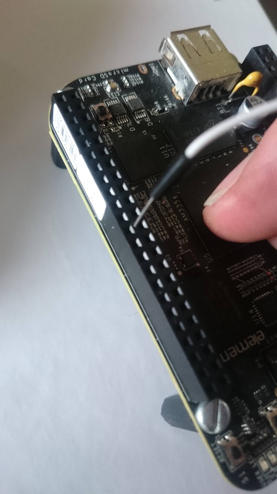
In case it helps, here are some photos of an FX18-60S-0.8SV10 (i.e. the
short version) while separate, partially inserted, and fully inserted: https://photos.app.goo.gl/N0bjus4GPxEFS4b63
Up until now, I’m really only used to interfacing sensors with BBB or RPi boards which allow standard jumper wires to make the connections:
I guess I’m trying to figure out what type of connector I need which will allow me to do the same with my X15 board:
The little holes at the base of the Hirose connectors on the X15 are too small to allow a jumper wire to be inserted. I was (and still am) assuming/hoping that there is some adapter or connector which will plug into the X15 connectors which will offer me the same sort of headers as the P8 and P9 on the BBB.
I hope that clarifies what I’m trying to do. I suppose the FX18-60S and FX18-60P connectors are designed for mating boards (such as LCD panel, etc.) together whereas I’m looking for a way to interface sensors via regular jumper wires.
The original X15 design had the same connectors as the BBB.
After insertion, you could not pull the boards apart without a very large and distructive screwdriver, due to the retention force (friction). That is why we went this route.
I have a design that provides adapters to give you these types of connectors. If someone wants to put them into production I would be happy to discuss this with them.
The connectors on the X15 are also suitable for high speed signals (USB3, PCI, SATA, etc), whereas the 0.1” connectors used on the BBB are not. Soldering wires onto a connector is not advisable because the pins are soft and will bend easily and probably touch adjacent pins which could cause permanent damage.
I agree with Matthijs, an adapter board is a good solution. Someone else posted pictures to this mailing list of an adapter board plugged into the X15. Maybe they can make their board available.
This looks good! In addition I have one for the SATA and the PCI that are located on one of the connectors. If anyone want to build and make these available, I will give them all the data and files.
Would you consider posting them on github or similar so that people can do this independently rather than need to organise a group buy / take on a large manufacturing run?
Here is my issue. If I put it on github for anyone to use, I will get questions on how to get it built and all sorts of technical questions and requests for changes. Questions, that honestly, I just don't have time to answer and changes that I don't have time to make.
I would be happy to turn it over to you to take care if you like. You can then use it as you wish and supply any required support.
As a relative novice to board fabrication - how might I check what this board physically looks like? I know from talking to some folks that the GERBER file is what’s required by the fabricator. I’m guessing I need to use specific software like Eagle or EasyEDA to view this?
I’m now being asked by the board fabricators to provide a “pick and place” and an assembly drawing in PDF format.
I have no idea what either of those things look like! The assembly drawing could be created from the schematic file I guess - were you asked for these items as well as the gerber zip file?