From that document you linked to:
PRU-controlled GPIOs are features I’m planning to make use of, so this is very relevant and significant information for me.
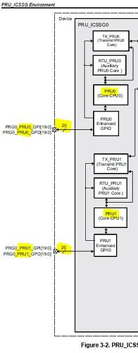
So it says 12 enhanced GPIs and GPOs. But which ones? According to Fig 3-2 (pg10 of this same document), there are 20 GPIOs that tie to those registers. Lower 12, upper 12? Anybody know or will this have to be figured out empirically? The brackets show [31:20] which would suggest the upper 12. However there were only 20 to start with and I didn’t think they extended all the way to 31. Regardless, as long as there are still 8 GPIOs that are working, that’s still OK for my needs. But knowing which bits are the active ones would be useful information.
It says specifically these are not supported in PRU0 for both PRU_ICSSG0/1. But what about PRU1? According to that same figure there’s supposed to be 20 on it. I can assume those are all present, correct?
Also the use of the word “enhanced” seems significant. Does that mean the new low-latency bi-directional support for GPOs that was introduced as part of the PRU_ICSSG subsystem? Or does this mean those GPIOs are unavailable/inoperable even using the pins the way the old PRU_ICSS did (as dedicated 1-directional GPIs or GPOs)? For those not familiar with the GPIO bi-directional enhancements I’m referring to, refer to this thread:
PRU_ICSS vs PRU_ICSSG wrt GPIO and bi-directional communications
I’m starting to see now why TI decided to just drop support for the PRUs in their official documentation so they didn’t have to clarify all these details.

