Okay and Still Trying with DM332T Drivers and a Logic Level Shifter

Hello There,

I am using a logic level shifter and some Python3 source to test the BeagleY-AI. My stepper motor driver is a DM332T.

This is the item for level shifting:

Has anyone used this level shifter successfully with the BeagleY-AI? If yes and if you have used it successfully, please reply with some type of data that I can use.

Seth

P.S. With the DM332T, my PSU/Bench Supply shuts down when I run the Python3 source which is found below:

#!/usr/bin/python3

import gpiod
import time

gpio12 = gpiod.find_line('GPIO12')
gpio12.request(consumer='beagle', type=gpiod.LINE_REQ_DIR_OUT, default_val=0)

gpio6 = gpiod.find_line('GPIO6')
gpio6.request(consumer='beagle', type=gpiod.LINE_REQ_DIR_OUT, default_val=0)


gpio13 = gpiod.find_line('GPIO13')
gpio13.request(consumer='beagle', type=gpiod.LINE_REQ_DIR_OUT, default_val=0)

try:
        gpio13.set_value(1)
        time.sleep(0.5)
        while True:
                gpio6.set_value(1)
                gpio12.set_value(1)
                time.sleep(4)
                gpio6.set_value(0)
                gpio12.set_value(1)
                time.sleep(4)
except KeyboardInterrupt:
        gpio13.set_value(0)
        pass
        print("Hey!")

I got most of the source from the docs.beagleboard.org page under the header BeagleY-AI.
Also, I found this data online but it has not proven valuable yet:

Also…it seems the driver is controlling the bench supply and not the motor.

I have tested everything available electrically. Things are panning out well in the test phasing but not in actual working applications. Send guidance and thank you!

Hi Seth,

What is your bench supply rated at ? I assume you are trying to pull too much current.
What is the stepper motor power requirements ?

Looking at your code, I assume

GPIO13 - ENA
GPIO12 - DIR
GPIO6 - STEP

You sleep(4) in the while loop are really way to long. You will be doing 1 step every 8 seconds. I doubt even if the power supply wasn’t turning off that your be able to tell that the motor was turning.

Try something like 0.01 instead, that will give you 50 steps per second.

The bench supply can handle 30v at 10A maximum. Ben, I set the current to 1.1A which is more than enough to handle the small stepper. I set the voltage to 12v too. This way, the driver sees itself as on.

Seth

P.S. I was in the sleep(4) for testing purposes. I really cannot figure out the issue. I will try 0.01 instead and see what happens. Thank you again for supporting the chat and forum here.

Other drivers work. These on the other hand have evaded me thus far! I have to work this Sat. So, I will be back later to test and I will then update the forum post.

What the resistance of the 2 colis on the stepper motor ?

At 1.1A it is probably current limiting especially if both coils are on at the same time.

1 Like

Assuming you have a switch mode psu you can find that switching loads can cause problems with over current protection

I will test the resistance on the two coils soon when running the source and yeppers about the coils being both on. I do not know what I am doing right now with this driver and source. So, please be patient.

Also, the PSU is a switching supply and I have noticed a glitch when running the source.

The current drops and then the twitching of the stepper stops. The voltage also drops from 12.4v to around 7v or 9v depending on the time.

I measured the voltage across the A +/- screw terminals and found the voltage to be extremely low while switching. I mean…0v to 0.4v.

Anyway, the boss called the whole entire Sat. off. So, I can test now.

I will test resistance now.

Seth

1.8 ohms.

Seth

P.S. That is the resistance. Let me check A +/- too. Brb…

Okay and so, they are slightly different. B +/- is 1.8 ohms while A +/- is 1.4 ohms.

Yeah you are going to need a lot more than 1.1 amps! Have you got a 12v battery handy ?

Yes and Yes. I have a 12v handy. I think they are rated at around 9AH.

And…this is a tiny stepper. This NEMA 17 stepper is made by Tronxy. I cannot remember where I got them but…

  1. It has eight pins out the backside of it.
  2. Four pins are used.
  3. Continuity is good on the motor winding with four pins used.

Seth

#!/usr/bin/python3

import gpiod
import time


gpio17 = gpiod.find_line('GPIO11')
gpio17.request(consumer='beagle', type=gpiod.LINE_REQ_DIR_OUT, default_val=0)

gpio27 = gpiod.find_line('GPIO13')
gpio27.request(consumer='beagle', type=gpiod.LINE_REQ_DIR_OUT, default_val=0)


gpio22 = gpiod.find_line('GPIO15')
gpio22.request(consumer='beagle', type=gpiod.LINE_REQ_DIR_OUT, default_val=0)

try:
        gpio22.set_value(1)
        time.sleep(0.5)
        I = int(input("Enter at will! "))
        while True:
                if I > 0 and I < 5:
                        gpio17.set_value(1)
                        gpio27.set_value(1)
                        time.sleep(0.1)
                else:
                        gpio17.set_value(0)
                        gpio27.set_value(1)
                        time.sleep(0.1)
except KeyboardInterrupt:
        gpio22.set_value(0)
        pass
        print("Hey!")

I changed the source and plugged in a 12v battery. Notta…

The motor is excited but cool still.

Seth

Also…

This is from stepper online, the company that “mfg” the parts (drivers).

It should be noted here that our DM320T and DM332T drivers do not have an ENA- terminal. The controller's enable signal output needs to be connected to the OPTO public port when connected. At this time, OPTO is equivalent to ENA+.

Also…on my side of things:

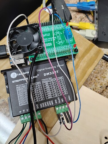
a. I have a USB C (of course) from the Y-AI to a USB 3.0 on a USB 3.0 port on the development desktop.

Here is the photo of the set up:

Do you think that maybe the Oono logic level translator is getting in the way of communication?

Also, do you think that i2c on the Y-AI is causing the Oono to act funny, i.e. making the GPIO chip malfunction?

Anyway, I can test the GPIO pins on the output. I will try another route if these GPIO pins I am using, 11, 13, 15, are not listening well. There are many on this board. Lots and lots of GPIO pins.

I looked at the header pinout on the docs and at GPIO at BeagleY-AI GPIO Pinout .

11, 13, 15 all seem like good pins to use and I was receiving some negative feedback from the Bench Supply PSU when switching the DIR and STEP pins on the Python3 source.

If you come up with some test procedures, please let me know. I have been reading about drivers recently and I found that drivers are intricate works of “art.” AC to DC is not an easy task…and then there is DC to DC which is probably more difficult.

Five key test points for understanding motor drive efficiency and performance | Fluke is something I was reading recently. It is more geared towards efficient maintenance of drivers and motors in general but useful to figure out what to test and what I should use for finding ripple and it even has math!

I would check the gpio pins after the level shifter with a scope. If they are toggling then that should be ok.

Not sure about the motor coil resistances, they are low but that could be normal.

Oh…

I checked the resistance on the terminal headers but without power. I will check the motor coils next. The spoiler is that I did check the resistance to the coils and made a error in remembering. And I will check the GPIO pins after the level shifter too.

Seth

P.S. But, as is say, they toggle (I think). I will test again…

FUBAR

you’re trying to drive optocuplers with a level shifter, not going to happen.
the level shifter you referenced has a 10K pull up, just not going to work.
look at figure #2 of the document i have referenced here.

2 Likes

also, not sure what the bby gpio can supply, but DM332T spec indicates up 16ma input current to drive the opto.

Okay…

No issue. I figured at least I could try…

Seth

so, using an op-amp for non-inverting amplifier may work or am I way off base here?

Seth

P.S. Or N-FET amplifier? I have a BC547 for amplification…

DM332T requires upto 16ma drive current.

1 Like

So, I need a current amplifier. Okay, I am working now to create a known working example.

Seth

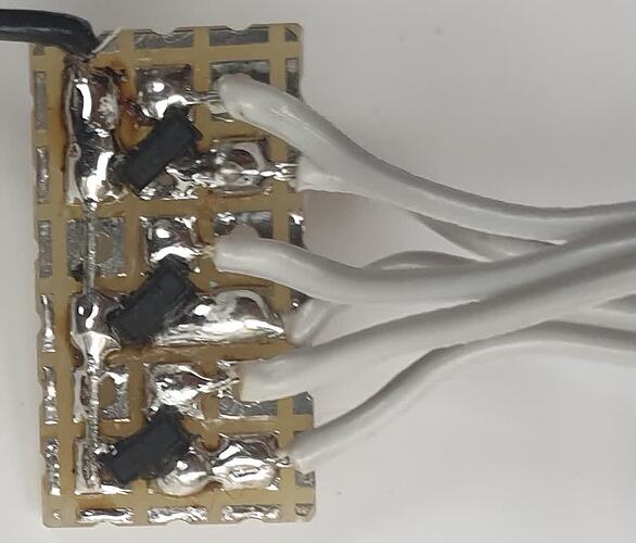
A FET is ideal here. Here is a pic of a quick and (very) dirty driver I put together a little while back using BSS138s - specificly for driving a stepper motor module very similar to the one you are using.

Another option if you need to drive several lines, is to use a cmos gate, such as a hex inverter - many cmos chips can drive 20 mA so can be used directly. (But tie any unused inputs high or low).