Okay. I have two N-FET BC547 transistors (BJT).
I will attempt these again and again. I have been trying with simulation software but I am not getting further along right now.
Seth
P.S. Thank you again.
Okay. I have two N-FET BC547 transistors (BJT).
I will attempt these again and again. I have been trying with simulation software but I am not getting further along right now.
Seth
P.S. Thank you again.
I just order some 74hc244 line drivers. Got the same problem as you with the low power SoC not having enough to drive an opto coupler.
Might try a mcp23017 and hang it on the i2c bus. Much simpler and it has enough juice to fire the stepper drive without intermediate remedies. If you don’t need precise timing it might be an option.
Looking at the schematic for that Pi logic level shifter, it is using FETs to do the level shifting and looks to rely on the body diode of the FET to sink GND. nad pullup resistors to give a high. Don’t know what the sink capability on the GPIO pins are, bearing in mind that the 16ma quoted in the datasheet is the max, but should still be catered for.
As I mentioned some time ago a simple NPN transistor is your best option here, with a suitable base resistor of course. Pretty any common BJT will do and your BC547 is fine. FETs will do, but smaller ones are usually surface mount and more of a pain to work with and you need to make sure they are logic level fets and will conduct at 3V.
As an alternative you could use a ULN2003 chip if you have one handy, in which case you don’t need the base resistor.
It is also worth getting some of the assorted component packs that Amazon sell ( at least in the UK). I have some boxes of transistors, fets, opamps, diodes, resistors and capacitors - ceramic and electrolytic. Very handy when putting stuff together and they are pretty cheap. Also worth getting hold of some surface mount carrier boards - might have to go to AliExpress. These have common smd footprints with through holes for connecting wires or header pins, usually on 0.1" spacing.
I will check my inventory for the ULN2003 chips. I see they come in PDIP packaging too!
TI is all out but Digikey has some, i.e. just in case I do not have them.
I have a On Semi/Fairchild BC547 set of two that I have found so far.
And A-Okay Ben, I will use the base resistor just in case. I am just prototyping for now. Until I can find the ULN2003 chips I think I have currently, I will test with the BC547 (which is now obsolete).
Seth
P.S. And about the SMD carrier boards for part injection, I have some that are PDIP so far but I will need to check to see which ones I currently have now. I have not used them so far…
pretty much any small NPN transistor should work.
these are quite good, depending on Amazon delivery costs -
BOJACK 12 Values 120 Pcs Opamp Timer Darlington Phototcoupler kit
this kit has the ULN2003 drivers.
Thank you…
Ben, I see. I have the NPN transistor(s) for this project. I have just reviewed some inventory:
I will keep searching for ULN2003 chips. I know I must have them somewhere…
Seth
I found a ULN2002. Blah. I am one number less. I will research these real quickly.
Ben,
So, I cannot get it…I am missing something still. I have the ULN2002 chips and some SN types.
I am using three GPIO pins for the ULN2002 and not receiving any movement on the motor…
The Bench Supply at least does not go into shutdown mode.
Seth
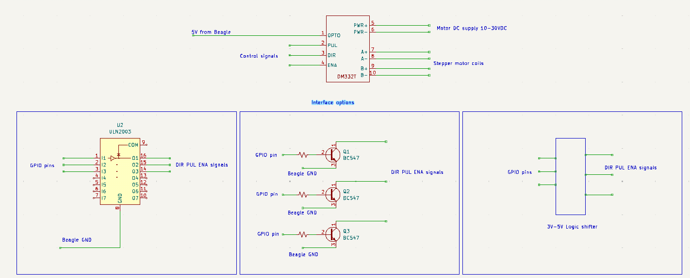
P.S. Should I skip the driver with these ULN2002 type Darlington Transistors? At first, I put the UNL2002 in the middle of the Y-AI and the DM332T. I can test without the driver…
the ULN chips can generally on sink upto 500ma per channel I think so you will need the DM322 driver for your NEMA 17s
Ok so somethings to check.
For starters according to the datasheet if you leave ENA unconnected, then the module is enabled by default. So to start with don’t connect ENA.
In that case with PUL and DIR disconnected.
The coils should be energised and the motor stiff to turn. Check the voltages and both coils, I would expect to see volts on both, but it might depend on the step sequence.
With PUL and DIR disconnected check the votage on the PUL and DIR terminal connections.
You should see 5V less the voltage drop of the opto isolator. No idea what that is, but would expect to see at least 2V though, probably closer to 4V
If you are reading nothing then the opto led is blown.
I don’t no how easy it is to get into the DM332, but with everything disconnected you could check the opto diode with a DVM in diode mode.
If you have some volts on those pins, connect up the ULN2002 and pulse the pins. Check with a scope is probably best to see that the PUL and DIR pins on the connector are going up and down.
If it is going up and down, then unless the opto diodes have blown shorted, the opto side of things should be good.
Without opening up the DM332 it is hard to check much more. You can put a scope on the coil outputs and see if you have any waveforms when stepping.
I can use the DMM and scope to check like you described here and I will…
Also, there are only two screws. The plastic case comes apart. I am beyond the replacement period. So, I will take it apart after testing with the DMM and scope…
Seth
P.S. I have tested three of these drivers. Something is up. Thank you again for helping me here…
Also, I have to go right now. I will be back later. bbl!
@benedict.hewson
those are n-fets in the level shifter. with the gate at 3.3, the gpio going low truns on the n-fet, the gpio must sink the 16ma to gnd when it is low. not sure what the bby gpio can sink to gnd.
Ben,
I am goofy here. So, I think I got it. COM is needed on this Darlington Array chip to handle inductive loads, e.g. MOTOR!
Since the phase is not known for a small period of time because of reactance, I am believing the discharge of caps in the PSU were excessive and caused the shutdown mechanism to turn it low and then in relation heat the motor.
Seth
P.S. Wait for testing to take place like discussed earlier. Anyway, I started a new e2e discussion and during my communication TO MYSELF in the “discussion,” it hit me about what I read and how it did not resonate to me. Inductive Loads…like motors or other types of chokes, need the Darlington Array chip COM to be utilized. Hmm…
Testing will unsue!
Should I use a diode? The ideas from the driver people, omc-stepperonline, state a 1k resistor for 12v supplies.
I think the voltage spikes that were causing the shutdown of the PSU were resultant of the heated motor. Ben, I will test with/without the flyback.
Seth
P.S. I test in time. No rush here!
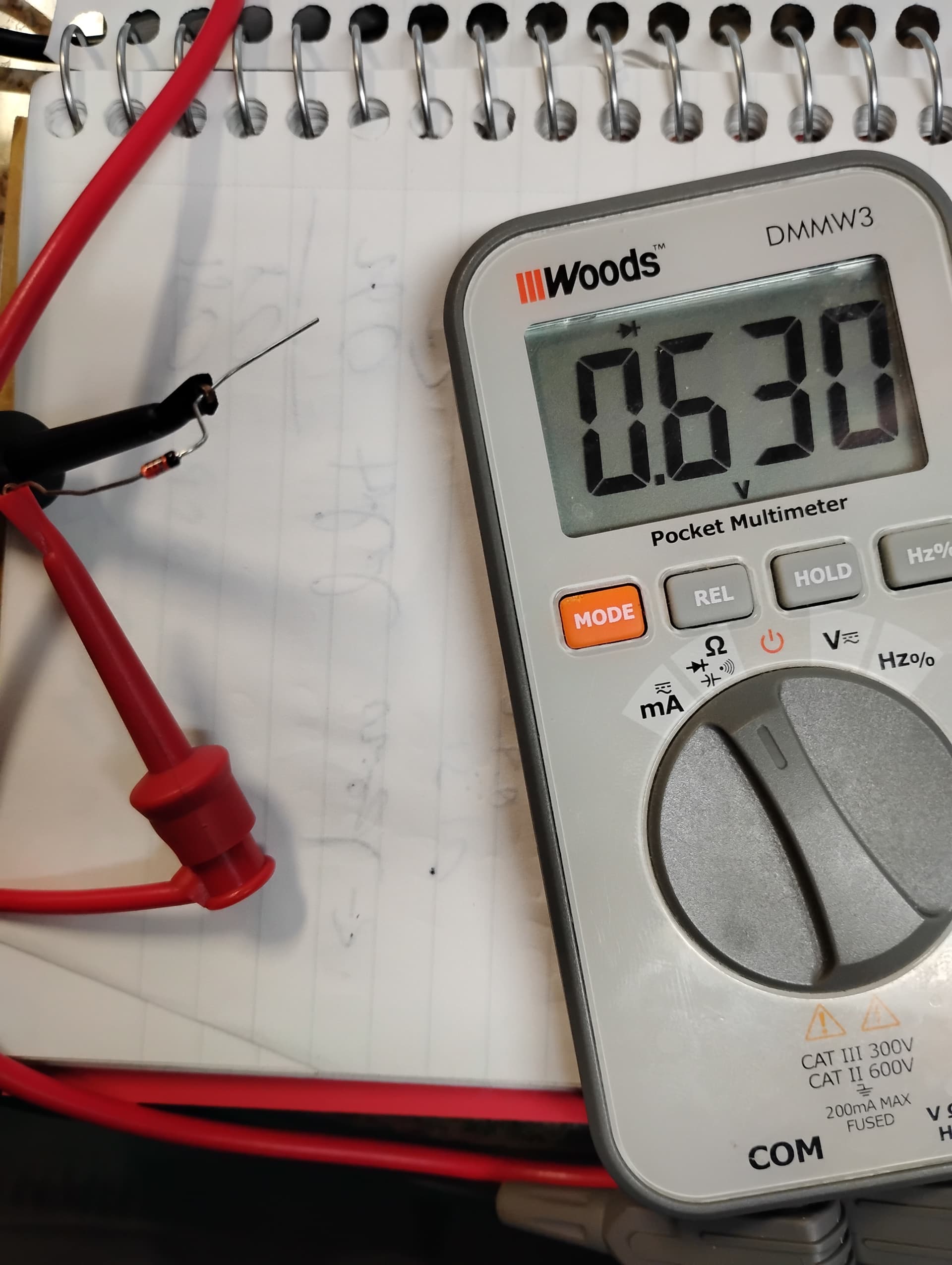
Also, my non-rewarding diode is missing a datasheet but I have measured the forward bias in this photo:
I have no way to tell what exact data comes with this specific diode. But, that is it…
0.59v is the oddity on the enable and OPTO pin(s)…
The reasoning for me stating “oddity” here is that I think the OPTO and EN pins are backwards.
I put COM on EN and diode mode V on OPTO and I get a NULL reading.
I reverse that setting and I get 0.59v.
Seth
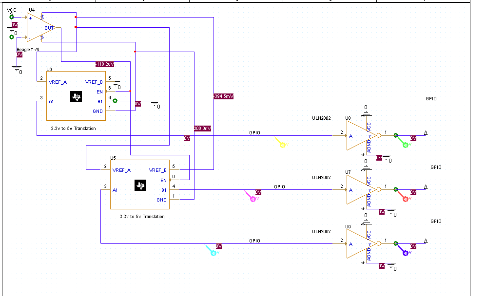
P.S. The easy route may be to get a new/older/different level shifter, I have this one Pololu - Logic Level Shifter, 4-Channel, Bidirectional , to account for level translation but I do not have a 5v source outside of this Y-AI and/or attached Logic Level Shifter…
I get 2.87v 0.07mA on GPIO17 pin 11 with the Hat attached.
I have not tested without the Hat attached recently.
Seth
P.S. I am going to take the Hat off and check it out… Okay, so.
I checked the voltage at 3.34 when powering the Y-AI without the Hat. This is good news (sort of).
I am trying with the logic level converter from Pololu and the ULN2002 for high mA switching of the GPIO pins. No luck so far…
I am grounding the ULN2002 and BeagleY-AI to the same GND.
I thought I should use the Pololu level shifter because of its wide range of accepted voltages.
I can use 3.3v in one end (GPIO) and export that voltage via a 5v source to 5v (GPIO) for external pin usage. The issue…
Okay. This will be my last transmission for the night, I hope.
# pins:

11 - GPIO17
13 - GPIO27
15 - GPIO22

# 11 is gpiochip2, pin 8
# 13 is gpiochip1, pin 33
# 15 is gpiochip1, pin 41
I have tried testing, running source, and some of what I can think about currently. Please send any guidance when you have time. Is pin 11 GPIO? Is pin 13 GPIO? Is pin 15 GPIO?
Maybe I am using pins 11, 13, 15 incorrectly?
Do you have an overlay installed to enable those pins? I don’t recall them being on by default, might be wrong on that its been a while since touching it.
Post a link to the exact image you have in your board and I will light one up.
Are you accounting for the fact that the ULN chip is an inverter? So you’ll need to invert the step, dir and ena outputs in your code, compared to what you were using before, without that chip.
No overlay. I am using GPIO by default (so I think). I have not even tested if the pins used are actually GPIO physically.
@bbbpaul ,
No, I am not accounting for the switch in I/O of the ULN chip.
From what I understand from the ULN2002, GND is GND and Input 1 is Output 1 and so on…
Seth
P.S. I see SPI and PWM take up a bit of pin usage, i.e. this makes me think that the GPIO pins are not available right now for my bidding even without the overlay(s).
Linux beagle 6.1.83-ti-arm64-r64 #1bookworm SMP PREEMPT_DYNAMIC Fri Sep 6 21:31:20 UTC 2024 aarch64 GNU/Linux
That is my image kernel…
here is the image:
BeagleBoard.org Debian Bookworm Xfce Image 2024-09-04
I built ~/opt/source/dtb-6.1-Beagle/build_n_install.sh and found an error in the .dtb for the kernel build.
I think something has been done but it is not used for successive parts. I do not know what I mean by that idea because I do not know why or for what reasons the .dtb is not built correctly for this kernel.
Seth
P.S. For now, there is nothing I can do. I may need to resort back to 5.10 or upgrade to 6.6? Alright, I am done trying to understand things for this night and today…
I have one photo that inexplicably does not tell the truth because Cadence does not cover all chips, e.g. ULN2002. I found one that is near it but still I return 0v on the simulation:
The ULN2002 does not accept TTL logic. The ULN2003 does support CMOS and TTL. Blah…
So, my logic level translator is getting in the way…
Ok yes looking at the ULN2002 datasheet, that won’t work, you need a ULN2003 and that works fine as I am driving a relay board with a ULN2803 (same as the ULN2003) directly from a BBB.
Yes you would not need to connect the COM pin as you are not switching an inductive load, just the E pin to GND.
I did say to leave ENA disconnected as the module is enabled by default, but the logic for this signal is inverted. Badly written datasheet in my opinion, so your Python code is wrong and setting ENA high is actually disabling the driver, so the stepping won’t work. This could be the issue when using the logic level shifter board.
It should be fine to connect the OPTO pin to the 5V of the Beagle. This should only be supplying the opto isolators and if driving all 3 signals should take no more than 48ma assuming worst case on the opto isolators according to the datasheet.
You should not need to connect the Beagle GND to the DM332T GND Thats the whole point of having the opto isolators on the input signals.
You have several options for controlling this, all of which should work. See diagram.
I strongly suggest leaving ENA disconnected to start with as that will enable the drivers. You can add it back at a later date once it is working.