Cool, glad that part is working.
1 Like
Hey Ben,
Okay…so finally these parts arrived and in condition. About to test now! Are you sure I do not need COM for the inductive load with 12v supplies on the ULN2003A chips?
I keep reading the datasheet and on “Chapter 8”, there is a small insert stating this fact:
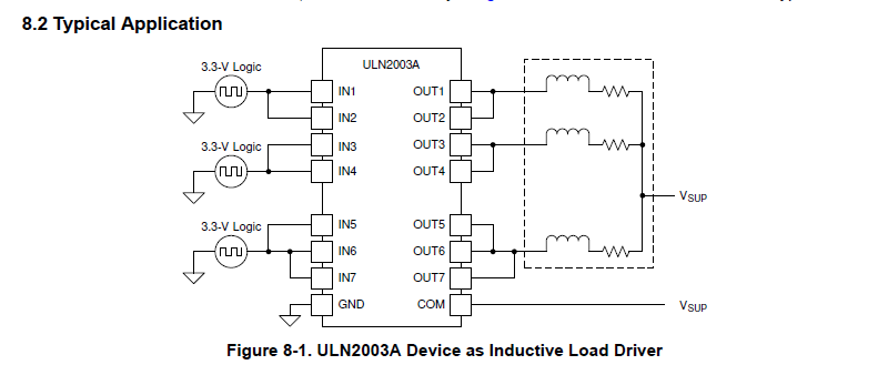
Also, the diagram shows controlling only three output pins, each with “floating pins” tied to them for output and input.
I understand that is one way and just a diagram of specifics. So, any feedback would be helpful.
If COM is not needed in my case, A-Okay.
Seth
P.S. The motor in question is an inductive load but not a large motor. So, I think the chip in of itself can handle it since we are using a driver too! Any ideas or feedback on what I am describing would be a nice thing. Please reply when you have time.
Update
Okay and NOW I see…the stated diagram is only if there is not a driver and bare.
I am using the ULN2003A as reference here…
The set up included is GND from the BBY-AI to E on the chip.
So,
- GND from BBY-AI to E on ULN2003A
- GPIO22 and GPIO27 from BBY-AI to ULN2003A to Driver
- 5v on BBY-AI to OPTO on the Driver (DM332T)
So, I am getting some movement, i.e. not much.
Seth
P.S. I think my source is goofy for now. I will be testing some other source soon.
Update
The source creates for movement (so I think).
The source compiles and runs. Right.
The motor jolts and does not move after the jolt.
Is there something I am missing in the build so far that is creating a jolt to no movement?
Oops…
Update Two
I took out the logic level translator. Blah…off to test with the level shifter back in the mixture!
Okay…
I am using a level shifter and the ULN2003A for testing this source:
// Testing...

#include <gpiod.h>
#include <stdio.h>
#include <unistd.h>
#include <errno.h>

#ifndef CONSUMER
#define CONSUMER        "consumer"
#endif

int main(int argc, char **argv) {
        const char *chipname0 = "gpiochip0";
        const char *chipname1 = "gpiochip1";

        unsigned int line_num1 = 7;     // Direction GPIO27 PIN 13
        unsigned int line_num2 = 33;    // Step GPIO23 PIN 16
        unsigned int val;

        struct gpiod_chip *chip1;
        struct gpiod_chip *chip2;

        struct gpiod_line *line1;
        struct gpiod_line *line2;

        int ret1, ret2;

        chip1 = gpiod_chip_open_by_name(chipname0);
        if (!chip1) {
                perror("The opening is failing...\n");
                goto end;
        }

        chip2 = gpiod_chip_open_by_name(chipname1);
        if (!chip2) {
                perror("No opening now...\n");
                goto end;
        }

        line1 = gpiod_chip_get_line(chip1, line_num1);
        if (!line1) {
                perror("Get line failed\n");
                goto close_chip;
        }

        line2 = gpiod_chip_get_line(chip2, line_num2);
        if (!line2) {
                perror("Get line failed\n");
                goto close_chip;
        }

        ret1 = gpiod_line_request_output(line1, CONSUMER, 0);
        if (ret1 < 0) {
                perror("Request line as output failed\n");
                goto release_line;
        }

        ret2 = gpiod_line_request_output(line2, CONSUMER, 0);
        if (ret2 < 0) {
                perror("Request line as output failed\n");
                goto release_line;
        }

        printf("All lines are not output...\n");

        for (val=0; val < 15; val++) {
                sleep(0.41);
                putchar('.');
                fflush(stdout);
                gpiod_line_set_value(line1, (val & 0x02) != 0);
                gpiod_line_set_value(line2, (val & 0x04) != 0);
                sleep(1);
        }

        printf("done...\n");

release_line:
        gpiod_line_release(line1);
        gpiod_line_release(line2);
close_chip:
        gpiod_chip_close(chip1);
        gpiod_chip_close(chip2);
end:
        return 0;
}
The source compiles and runs. This is okay news but I only receive the jolt and then it goes back to where it started before the jolt of movement. Like it is a locking mechanism. Maybe I used this source for a locking solenoid in the past. Hmm?
Anyway, the source is working but the source is a bit off. I understand this is of concern. I will learn more in time but until then, I am at a standstill in source versus motor movement. Off to test…
Seth
P.S. Without using some compilation efforts on my part, the source does not run but errors out with a segmentation fault. I mean it. Even with gcc MY_FILE.c -lgpiod -o my_file for compilation, I receive some erroring that I am not accounting for currently. I have no way to tell what exactly is going on without more investigative work.
This link was the start of understanding the movement of a GPIO * 3 while attempting some logic to create a bipolar stepper to move around some…
Thank you @bbbpaul for starting it all with some good ideas…
Ben,
I was on a tester image… Blah. I have rebooted into a known working image. I will test my findings with this new image from 2024 and test from that point forward.
Seth
P.S. I think I got the image somewhere outside of the bb-imager or I got the testing image from the image section on the beagleboard.org website.
Hi Seth,
So you do not need to connect the COM pin. You are not switching an inductive load, just turning on an LED. It won’t hurt if you connect it to 5V though.
So you need to do some good testing here, one step at a time.
So to start, get rid of the level shifter, you should not need it and it is just another component that can complicate things. If you can set the voltage range such that it doesn’t auto switch ranges that would help, or you might need to go slower.
So at a minimum to turn the motor to test we just need the PUL pin, but you can check the other GPIO pins while you are at it.
For testing if using a DMV. If using a scope use usleep(5000);]
I don’t know which pins are which but suggest test first the PUL pin and then the DIR and ENA pins.
       // remove your for loop and replace with this
        while (1){
                gpiod_line_set_value(line1, 1);
                sleep(3);
                gpiod_line_set_value(line1, 0);
                sleep(3);
        }
Step 1.
Power up the beagle but connect nothing.
Now you can either use a DVM or a scope. If using a DVM you will need to make sure that your code toggles the pin very slowly, something like 3 seconds on, 3 seconds off. This will depend on the update rate of your DVM.
Check that the GPIO pins are going up and down. If not you have a pinmux issue. Fix and repeat step 1 until you have control of the pin.
You can check all of your GPIO pins in this step.
Step 2.
Connect beagle 5V to opto.
Connect beagle GND to E pin.
Connect GPIO pin to ULN2003 input.
Connect ULN2003 out to PUL on driver.
No other connections on the driver.
Run your test code again.
Check the input to the ULN2003 is going up and down - it should be if you pass step 1.
Check the voltage on the PUL connection on the driver. You should see this also going up and down at the same rate.
If the PUL connection is not going up and down there are a couple of possible reasons.
a. The beagle can’t drive the ULN2003 (unlikely)
b. The opto part of the optoisolator has blown,
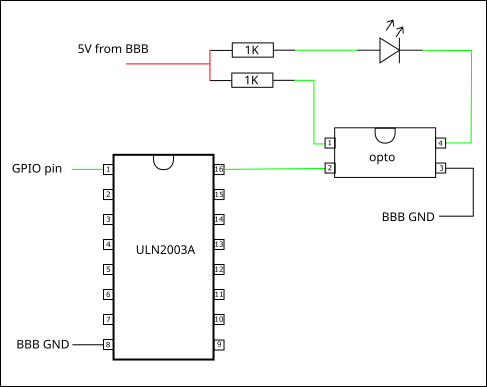
To test (a) you can try switching an LED if you have one. Connect a 1K resistor to 5Vm the other end to the anode of the LED. To make sure your LED works, connect the cathode to GND and it should light. If not you either have the LED back to front or it is no good.
Now connect the cathode to the output of the ULN2003 and run your code and the LED should blink.
If that works then you probably have a blown optoisolator in the driver.
You can use the same pin to test each input on the driver module. You should see the voltage go up and down.
If you have passed Step 1 and Step 2
Step 3.
Wire up a motor and connect the motor supply. Make sure you set a reasonable current limit…
With just the GPIO connected to the PUL input, run your code and pulse the pin. You will need to do this quickly if you are to see the motor move. A scope to check this pulse rate would be good.
If the motor turns all good. If it doesn’t try connecting the ENA pin on the driver module to Beagle GND. If it still doesn’t turn then you either have a problem with the driver module or your motor.
Try those 3 things first and see where we get to.
usleep(410000); // 410 milliseconds
Also add some perror or try and catch statements when you open the gpio up. It might be failing to open the line and that is your seg fault.
Try this, it is hybrid code, c with c++ exception handling. This will help locate the issue. I don’t have a board up and running at this moment so this code might fail. However it should be a guide. It has the familiar c code yet leverages the power of c++.
g++ -o hybrid_gpio hybrid_gpio.cpp -lgpiod
#include <gpiod.h>
#include <iostream>
#include <stdexcept>
#include <unistd.h>
#include <cerrno>
#include <cstdio>

// Macro for the consumer name
#ifndef CONSUMER
#define CONSUMER "consumer"
#endif

// Function to wrap chip opening with exception handling
struct gpiod_chip* open_chip(const char* chipname) {
    struct gpiod_chip* chip = gpiod_chip_open_by_name(chipname);
    if (!chip) {
        throw std::runtime_error(std::string("Failed to open chip: ") + chipname);
    }
    return chip;
}

int main(int argc, char** argv) {
    const char* chipname0 = "gpiochip0";
    const char* chipname1 = "gpiochip1";

    unsigned int line_num1 = 7;     // Direction GPIO27 PIN 13
    unsigned int line_num2 = 33;    // Step GPIO23 PIN 16
    unsigned int val;

    struct gpiod_chip* chip1 = nullptr;
    struct gpiod_chip* chip2 = nullptr;
    struct gpiod_line* line1 = nullptr;
    struct gpiod_line* line2 = nullptr;

    try {
        // Open the GPIO chips with exception handling
        chip1 = open_chip(chipname0);
        chip2 = open_chip(chipname1);

        // Get the GPIO lines
        line1 = gpiod_chip_get_line(chip1, line_num1);
        if (!line1) {
            throw std::runtime_error("Failed to get line1 from gpiochip0");
        }

        line2 = gpiod_chip_get_line(chip2, line_num2);
        if (!line2) {
            throw std::runtime_error("Failed to get line2 from gpiochip1");
        }

        // Request the lines as output
        if (gpiod_line_request_output(line1, CONSUMER, 0) < 0) {
            throw std::runtime_error("Failed to request line1 as output");
        }

        if (gpiod_line_request_output(line2, CONSUMER, 0) < 0) {
            throw std::runtime_error("Failed to request line2 as output");
        }

        std::cout << "All lines are now output..." << std::endl;

        // Toggle the lines in a loop
        for (val = 0; val < 15; val++) {
            usleep(410000); // Sleep for 410ms
            std::cout.put('.');
            std::cout.flush();
            gpiod_line_set_value(line1, (val & 0x02) != 0);
            gpiod_line_set_value(line2, (val & 0x04) != 0);
            sleep(1);
        }

        std::cout << "\ndone..." << std::endl;

    } catch (const std::exception& ex) {
        // Handle exceptions and print the error
        std::cerr << "Error: " << ex.what() << std::endl;
    }

    // Cleanup resources
    if (line1) gpiod_line_release(line1);
    if (line2) gpiod_line_release(line2);
    if (chip1) gpiod_chip_close(chip1);
    if (chip2) gpiod_chip_close(chip2);

    return 0;
}
Okay. I will attempt 1, 2, 3 and repeat until satisfaction.
I have already seen the DMM in voltage mode account for the GPIO pins in question:
GPIO27 PIN 13 # is actually GPIOCHIP0 at line 7
GPIO23 PIN 16 # is actually GPIOCHIP1 at line 33
Both are accounted for currently and working. Also, the ULN2003A chip is fine. I tested it with and without the EN as GND and OPTO as GPIO. I also tested with EN as GND and OPTO as GPIO.
When I tested without EN as GND, OPTO was a 5v source to power the driver innerworkings.
I also tested on the opposite side of the chip (ULN2003A). It is the PDI package. Easy to test…
I just plug in a wire with a bare end and attach it to the DMM and let the sparks fly. ha. Just kidding.
I really just test the GPIO changing voltage.
Now about this darn driver (DM332T). Luckily, they are very inexpensive. I purchased three of them, i.e. all with different outer signification. Anyway and so:
- Maybe the GPIO at 5v from the level shifter to the ULN2003A created a misnomer of sorts. Heh? I am solely discussing the mismanagement of the driver on my part.
- I could have mismanaged the driver on many accounts during owning it but my notes are from memory. I have no hard copies and what is simplistic is bypassing my state.
- I have paid close attention to 5v supplies or 4.5v ~ 5v supplies either via GPIO and/or 5v steady current along with what I described in what I said about testing EN, GND, OPTO and so on…
I have repeated the same action so many times, I overwhelmed myself and then it worked!
I have the source of it working but the output is not as expected. I was not expecting a full blown run to a brake and then to a couple of jolts going either way repeatedly.
This was confusing at first. The source halts the driver from understanding to keep jolting once CTRL-C is applied.
CTRL-C and the cancellation of the running source from within the source have been abbreviated so to say. I could go on and on.
The canceled source from within gpiod.h that is made available these days has been a cure of sorts. I am dimwitted and recursive.
Recursive in that I AM THE MATH FUNCTION and not relating to computers at all. I just keep repeating the same thing. I am the dawg gone if statement (a cyclic if).
Anyway, enough about me. Ben, I will attempt this “ordeal” again and again until completion. Even though it is trying on me, I am enjoying thinking I can learn something. I know testing must ensue and accounting for peripherals working while testing is necessary on various sides of applications and chips (I/O).
I just do not want to rip off pigpio or gpio zero. I am learning and not communicating to advance in copycat stuff. I know…
Most things we can think about have already been done and done again. I just want to pretend I am smart at times. So, if I say I made it, I made it! Another one for the books and future notes.
Seth
P.S. I may have STEP and DIRECTION confused too. Time will tell.
I am just getting back to you Ben now because of my awesome day at Lolliland. I have had to mow a field of death for small income amounts. Got to keep these teeth white as can be now! Who knows will Miss Mississippi walks through the door? All jokes aside, testing will ensue. BBL!
I may test it. I will let you know. I am so close on my odd source, I can feel the heat of the motor.
Also Ben,
Check out what I can configure now!
I can finally set up data correctly without being overwhelmed like in an earlier post in this 69 posted message center:
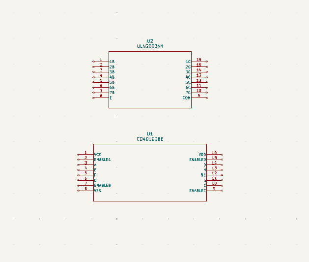
I was thinking of using the CD40109B alongside the ULN2003A for attempting power “achievements.”
Anyway, I may not now that I seem to be having a bit of trouble so far. I may play lowkey and out for Sat. while I regroup.
Seth
Aw and dang it:
I should have listened…
I did not apply 5v 3A supplies to the BBY-AI yet. Blah…I will attempt this set up with the proper hardware and voltage * amperage. Blah again…
hey!
I am an idiot! Well sort of an idiot for now, I did not test my PSU. My PSU, as presumed, was busted…
Now the PSU shuts down and cannot allocate enough amperage to the motor driver. Blah…
This is giving me some credentials back, i.e. as I could have tested the PSU with a DMM and not gone by what it states on the display. Argh…
@foxsquirrel and @bbbpaul and @amf99 and @benedict.hewson ,
Sorry. I canceled my need to supply myself with learning by testing and found myself in a rut.
Off to find a new supply.
WHOOOOOOOOOOOOOOOOOOOOOOOOOO! ha…
1 Like
Dang It Ben,
Seth here. I think I have cracked the case on this one…
4.17v is as HIGH as I can get with the translator and ULN2003A from the GPIO on the BY-AI.
I am about 0.00v off, i.e. as I can use 4v to 5v for enabling the DIR, STEP, and OPTO pins for use…
It is almost like it was not meant to be…
Pulse active at rising edge; 4-5V when PUL-HIGH, 0-0.5V when PUL-LOW.
Minimal pulse width of 2.5μs. The same as DIR and ENA signals.
The above excerpt is from the manual for the driver in question.
I guess using the rising edge may prove more valuable, i.e. instead of using HIGH or LOW alone.
Seth
P.S. I am on the mission to find the correct Rising Edge voltage without it understanding the GPIO is pulled HIGH with a waiting period. If anyone has any other ideas, please do reply.
Just to Say Here
The pull HIGH of the GPIO with the circuitry, again, is about 4.17v which is in the realm of correct here says the driver datasheet.
############
###Update###
###########
Okay…so. I see the low of my GPIO is too high. I am almost at 0.7v. How would I set up a GPIO on the BY-AI to support lower voltage at one section of the spectrum (LOW) and higher voltage on the other end of the spectrum (HIGH)?
I think this is the cause of my error in usage so far. The GPIO does not go LOW enough and the spectrum is CMOS and NOT TTL logic but 5v CMOS. I think this is where I have been mistaken here…
Off to research more again and again.
And More Data
I am getting 2.43v going one direction to the next. So…
It goes from 0.674v to 2.43v to 4.17v. Okay…so floating. I am having floating pins somewhere.
The pins, these GPIO pins, never go back to floating at 0.674v from Rising to HIGH to Falling to LOW. It only goes from floating to Rising to HIGH to Falling to LOW. Off to reorganize. Argh…
Ben, I am in fact driving an inductive load. This is not a fan or PWM signal notifying my heater of an excessive amount of time and heat. I am driving a motor.
I think because of what the chip states in the datasheet, I should use the pin in question because of me using an inductive load from the ULN2003A to the…oh.
Dang it. Okay, okay, okay. So, because the driver is middle man here in between the ULN2003A and the motor, GND is used instead of a COM pin. Okay. Just so we are straight here....
Update
I just understood what you are attempting here with my quote of the day from your past understanding.
This confused me at first. You say we are not, or I am not, switching inductive loads but I am switching inductive loads but not in the same context.
And E is loaded to GND but what GND, the BY-AI or the EN on the driver?
I am running in circles here. No issue. I will keep attempting things…
DM332T module is driving an inductive load, but that is all handled by the module. The whole point of having the opto-isolators on the signal pins is to isolate whatever you are using to driver the module.
Assuming the module is designed properly there is no connection from the OPTO, ENA, DIR and PULSE pins to any of the electronics that is actually driving the motor.
As for connections the OPTO connection should be tied to the Beagle 5V supply.
The en pin on the ULN2003 must be connected to Beagle GND. It is the return current path for the 5V on the OPTO pin.
Three of the outputs of the ULN2003 are connected to the ENA,DIR and PULSE pins on the module.
The corresponding inputs on the ULN2003 are connected to GPIO pins.
Thats it, nothing else.
2 Likes
So, no level shifter…
Is that right? Should I use a level shifter at all? I will keeping trying.
no need for a level shifter.
Just to verify I hooked up my BBB directly to a ULN2003A chip. I also added a opto-iosolator on the output and then just to see if it worked added an red LED on the output side of the opto-isolator.
Ran the test code (that I emailed you) to toggle the GPIO pin and the LED on the isolated side flashes as expected.
1 Like
I wrote my own DTC/DTS file and it compiled!
Anyway, I will take out the Level Shifter. Thank you Ben.
Seth
this is basically my test circuit.
1 Like
I think I set up everything correctly.
The drivers must be garbage. Literally, I have two GPIO pins and GND plus the 5v supply for the OPTO pin(s).
I typed pin(s) because I have tried three, separate drivers of the same type so far with the BeagleY-AI.
I know the GPIO pins are working. I have seen them work on record while testing but I have been unable to use these specific drivers.
Seth
P.S. I even had a ill-fated set of troubles with a 32-bit machine with these drivers. Argh…
Anyway…check this out:
/dts-v1/;
/plugin/;

#include <dt-bindings/gpio/gpio.h>
#include "ti/k3-pinctrl.h"

/*
 * Helper to show loaded overlays under: /proc/device-tree/chosen/overlays/
*/

&{/chosen} {
        overlays {
                beagley-ai-gpio-three.kernel = __TIMESTAMP__;
                hat_gpio.600000.gpiod = "beagley-ai-gpio-three.600000.1.GPIOD";
                gpio.600000.gpiod = "beagley-ai-gpio-three.600000.1.GPIOD";
        };
};

&main_pmx1 {
        hat_31_gpio: hat-31-gpio-pins {
                pinctrl-single,pins = <
                        J722S_IOPAD(0x1BC, PIN_OUTPUT, 7) /* N22 and B5 and P26 */
                >;
        };
        hat_11_gpio: hat-11-gpio-pins {
                pinctrl-single,pins = <
                        J722S_IOPAD(0x198, PIN_OUTPUT, 7) /* N22 and B5 and P26 */
                >;
        };
        hat_29_gpio: hat-29-gpio-pins {
                pinctrl-single,pins = <
                        J722S_IOPAD(0x1B4, PIN_OUTPUT, 7) /* N22 and B5 and P26 */
                >;
        };
};

&GPIO1 {
        pinctrl-names = "default";
        pinctrl-0 = <&hat_31_gpio>;
        status = "okay";
};

&GPIO2 {
        pinctrl-names = "default";
        pinctrl-0 = <&hat_11_gpio>;
        status = "okay";
};

&GPIO3 {
        pinctrl-names = "default";
        pinctrl-0 = <&hat_29_gpio>;
        status = "okay";
};
That is only for GPIOCHIP0! It does not work so far…I could not get the .kernel to show under /proc/device-tree/chosen/overlays/ for some reason. It may work but the driver is giving me issues, i.e. so I am stuck with three bad drivers, a lot of headaches, and too much running source for no reason. Argh…