PocketBeagle headers

I got myself a PocketBeagle and I realized that I cannot fit headers on the CPU components side because there is not enough clearance between the pads and the Octavo chip for the plastic of the header to fit in. I am using headers like these https://www.adafruit.com/product/2076, these https://www.mouser.co.uk/ProductDetail/Gravitech/20Mx2-254mm or sockets like these sockets https://www.mouser.co.uk/ProductDetail/Gravitech/4Fx2-254mm/
None of these would fit.

The alternative would be to place the sockets on the bottom side and put the solder on the components side, but it does not seem a great option. Are there any sockets/headers that you use that fit on the components side?

I have installed my headers on the bottom. They do not fit on top. I also figure that this is best so I can heatsink the Octavo chip if needed.

I've gotten both dual row and single row female headers to fit..

The secret, use a "CLICK" board to help keep it aligned..

Single row push hard enough and it'll fit around the Octavo

Dual Row, they'll be a gap, but enough room to solder:

See the pictures as an example:

Regards,

IMG_20170929_092848.jpg

IMG_20170929_092602.jpg

IMG_20170929_092653.jpg

I got myself a PocketBeagle and I realized that I cannot fit headers on the
CPU components side because there is not enough clearance between the pads
and the Octavo chip for the plastic of the header to fit in. I am using
headers like these https://www.adafruit.com/product/2076, these
https://www.mouser.co.uk/ProductDetail/Gravitech/20Mx2-254mm or sockets like
these sockets https://www.mouser.co.uk/ProductDetail/Gravitech/4Fx2-254mm/
None of these would fit.

The alternative would be to place the sockets on the bottom side and put the
solder on the components side, but it does not seem a great option. Are
there any sockets/headers that you use that fit on the components side?

I’ve gotten both dual row and single row female headers to fit…

The secret, use a “CLICK” board to help keep it aligned…

Single row push hard enough and it’ll fit around the Octavo

Dual Row, they’ll be a gap, but enough room to solder:

See the pictures as an example:

BTW, we are looking at creating an add-on specification. Feedback from the community is critical.

Yes, indeed, we know the fit around the Octavo SIP is tight for shrouded connectors. This was to enable use of mikroBUS Click boards (two of them). Robert has shown how it is indeed possible.

Some conventions it seems we should encourage such that people making add-on daughterboards do them consistently. Feedback requested here.

  • Always put female headers on top and male headers on bottom.
  • Pass-through headers are fine.
  • If populating for a breadboard, try to use the outer rows and use only one-side per board (don’t try to span or you won’t have a place to put your wires where you can see them.
  • Add-on daughterboards should tend to use male headers on the bottom, exposing the silkscreen on PocketBeagle’s bottom for easy probing.

These are just some thoughts from someone who has been prototyping with the boards for a couple of weeks. The point is to provide feedback. Please chime in on each point feel free to “pile-on” in the feedback. It can be annoying for some people not interested, but should be OK if we keep it to ONE THREAD.

Some concerns about my thoughts, right off the bat.

  • Using the silkscreen is difficult if you keep the board upright, so putting male headers on bottom makes prototyping on a breadboard difficult.
  • Having male headers on bottom could easily result in shorts when setting the board down.
  • Ribbon cables and the Pi-style breakouts to breadboards could work if male headers were put on top.
  • Any headers on the bottom will make fitting in the Altoids Smalls mint tin more difficult.
  • Breadboarding often is useful for SPI/I2C/UART devices or 5V/3.3V output not available on the outer rows by default.

Some alternate thoughts that support my initial position.

  • The headers are positioned to work with Click boards on top. This is something I might have changed if we did it over, but my sensibilities tell me the components should be top-side on all boards.
  • If breadboarding, you can always use female headers on top, as suggested, and use male-pins to act as an interposer, flipping the board and selectively placing those male pins on either the inner or outer row. To that end, I might suggest never soldering male headers on the bottom at all, but I can imagine many cases where that is desirable.

OK, I had a lot more on my mind, but time for me to say less-about-me-and-more-about-you. Pile on! (Please use in-line comments to make the thread readable, rather than just throwing your comments on top.

I got myself a PocketBeagle and I realized that I cannot fit headers on the
CPU components side because there is not enough clearance between the pads
and the Octavo chip for the plastic of the header to fit in. I am using
headers like these https://www.adafruit.com/product/2076, these
https://www.mouser.co.uk/ProductDetail/Gravitech/20Mx2-254mm or sockets like
these sockets https://www.mouser.co.uk/ProductDetail/Gravitech/4Fx2-254mm/
None of these would fit.

The alternative would be to place the sockets on the bottom side and put the
solder on the components side, but it does not seem a great option. Are
there any sockets/headers that you use that fit on the components side?

I’ve gotten both dual row and single row female headers to fit…

The secret, use a “CLICK” board to help keep it aligned…

Single row push hard enough and it’ll fit around the Octavo

Dual Row, they’ll be a gap, but enough room to solder:

See the pictures as an example:

BTW, we are looking at creating an add-on specification. Feedback from the community is critical.

Yes, indeed, we know the fit around the Octavo SIP is tight for shrouded connectors. This was to enable use of mikroBUS Click boards (two of them). Robert has shown how it is indeed possible.

Some conventions it seems we should encourage such that people making add-on daughterboards do them consistently. Feedback requested here.

  • Always put female headers on top and male headers on bottom.
  • Pass-through headers are fine.
  • If populating for a breadboard, try to use the outer rows and use only one-side per board (don’t try to span or you won’t have a place to put your wires where you can see them.

That is the reason why we thinned out the number of pins to a single row on our Letux Cortex 8 OSD3358 board.

  • Add-on daughterboards should tend to use male headers on the bottom, exposing the silkscreen on PocketBeagle’s bottom for easy probing.

Sounds very reasonable.

The only downside I see is that you can’t press the reset button or see the LEDs.

These are just some thoughts from someone who has been prototyping with the boards for a couple of weeks. The point is to provide feedback. Please chime in on each point feel free to “pile-on” in the feedback. It can be annoying for some people not interested, but should be OK if we keep it to ONE THREAD.

Some concerns about my thoughts, right off the bat.

  • Using the silkscreen is difficult if you keep the board upright, so putting male headers on bottom makes prototyping on a breadboard difficult.
  • Having male headers on bottom could easily result in shorts when setting the board down.

well, female on top still have metal pins standing out of the bottom side, but it might be easier to protect.

  • Ribbon cables and the Pi-style breakouts to breadboards could work if male headers were put on top.
  • Any headers on the bottom will make fitting in the Altoids Smalls mint tin more difficult.
  • Breadboarding often is useful for SPI/I2C/UART devices or 5V/3.3V output not available on the outer rows by default.

Some alternate thoughts that support my initial position.

  • The headers are positioned to work with Click boards on top. This is something I might have changed if we did it over, but my sensibilities tell me the components should be top-side on all boards.
  • If breadboarding, you can always use female headers on top, as suggested, and use male-pins to act as an interposer, flipping the board and selectively placing those male pins on either the inner or outer row. To that end, I might suggest never soldering male headers on the bottom at all, but I can imagine many cases where that is desirable.

Female headers on top is also the default of the BeagleBone. So it has become sort of “Beagle”-standard…
So it seems to be quite “natural” to me.

I have thinned out the EAGLE files so that only the board dimensions and the contact pads and the silk screen (so that a daughterboard can have the same bottom print - but uses male headers):

https://www.goldelico.com/downloads/PocketBeagleCape.sch
https://www.goldelico.com/downloads/PocketBeagleCape.brd

Maybe you could publish an “official” blueprint like this somewhere and recommend headers for PocketBeagle and a Cape.

BR,
Nikolaus Schaller

In looking for a female header receptacle to fit on the top of the board, to accept the Click ETH-WIZ Ethernet daughter card, so far, I have only found one brand of receptacle that I can make fit.

I would normally expect connectors for the 0.1 inch grid system to be 0.100 inches wide for single row, and 0.200 inches wide for the dual row.

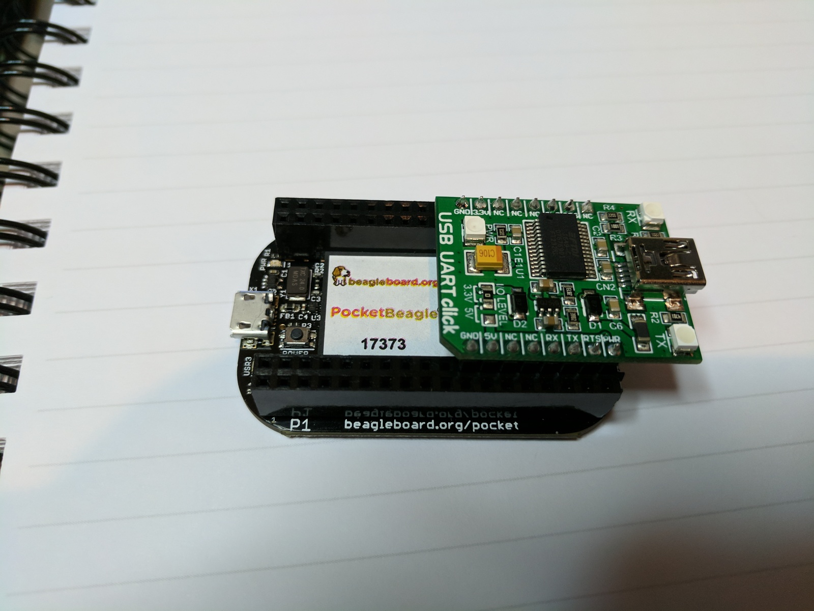
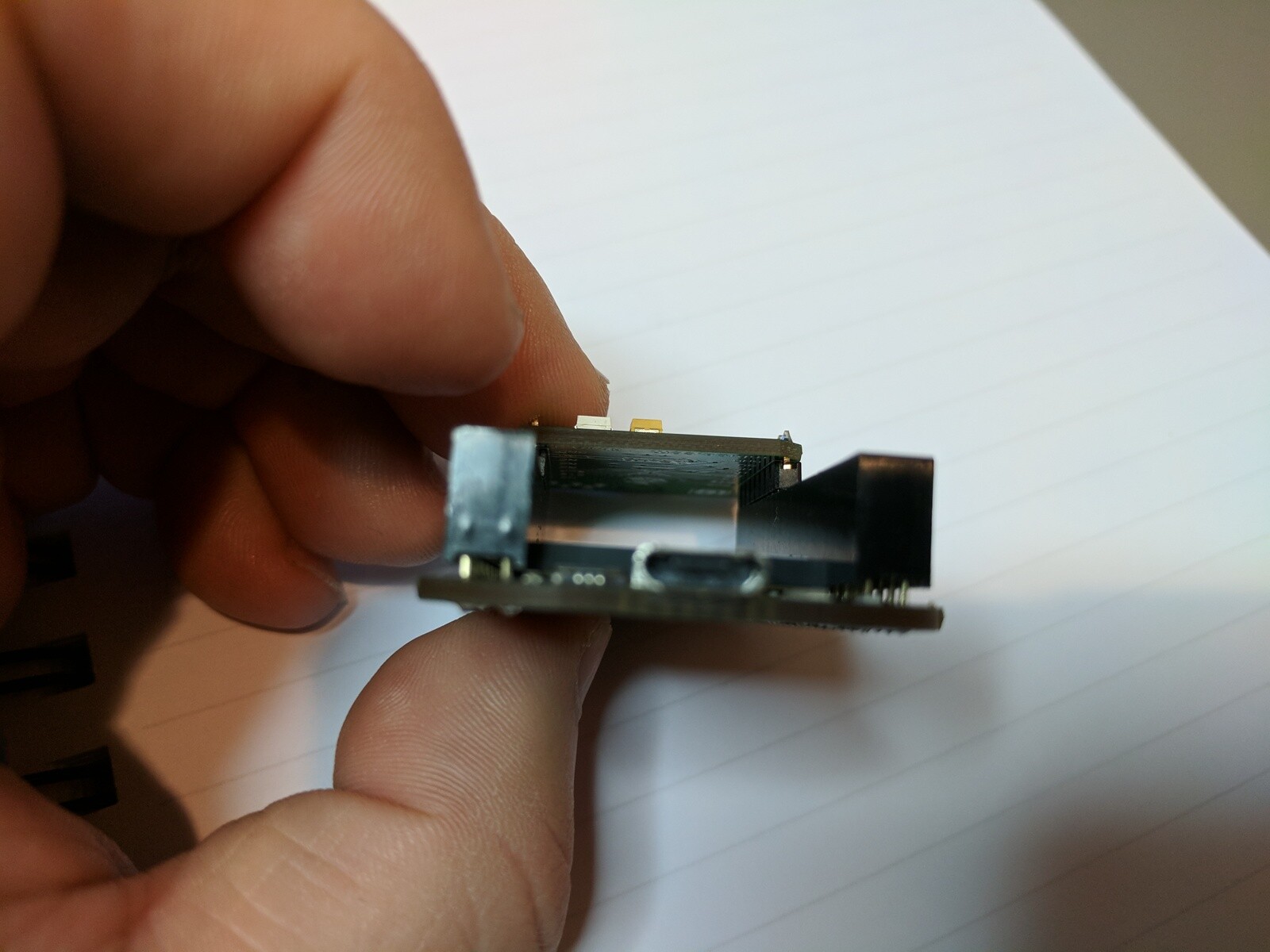
The Molex CGrid-III series, dual row female, is only 0.195 inches wide at the base and will fit on either side of the Octavo chip, and also fit flat against the PC board, without forcing, so the connector is vertical.
Line-to-line fit without clearance, but it does fit.

The 3M series is 0.201 inches wide at the base, and there is no way to use that connector on the PocketBeagle.

I have some Amphenol-FCI connectors on order, but they were delayed in shipping, so no results yet.

The Molex cost more, and are only stocked in distribution with tin mating surface (gold flash exists, but no stock found in distribution.)
The Molex is not available in a 36 pin version (18x2), but you can do something like a 20 and a 16 to populate all positions. (an 18 pin exists, but no stock found in distribution.)

Molex C-Grid-III series, dual row female, tin contacts
Following stocked at both Mouser and Digikey

90151-2116 16 position (8x2)

90151-2120 20 position (10x2)

If someone has another vendor and part number that will fit, I would like to hear about it.

— Graham

I generally agree with Jason’s proposed “standards.”

Female headers facing upwards.
Male pins facing downwards.

The “Click” boards already do this and come assembled with male header pins facing downwards.

The BeagleBones already do it this way.

But there do have to be readily available parts that allow you to implement the hardware standard, without forcing things to fit.

— Graham

For female headers, there's got to be a "thiner" side version made by
someone.. I thought about lightly belt sanding one too see how close
we could get it.

Regards,

evilwulfie wrote:


check out samtec

Yeah, if we can get a part number, i'll push it up the grapevine.. :wink:

Regards,

Robert:

OK. I found a Samtec part that will probably fit, but will need to get some samples and try it.

The part numbers are already set up in Digikey’s system, but not stocked, quoting large minimum quantities and three week delivery.

Can you get samples from Samtec? Or, I can call in a favor from the local Samtec rep. (He probably can’t get sales credit for an end-sale to Digikey.)

These are both 0.195 inch wide (nominal).

18x2 positions, gold flash on contacts, tin plated solder tabs for through hole on PCB. Samtec # ESW-118-12-F-D

or

18x2 positions, tin plated contacts, tin plated solder tabs for PCB through hole. Samtec # ESW-118-12-T-D

I personally prefer gold on gold for signals, but costs a dollar per connector more. (Google “tin fretting”)

— Graham

Samples ordered.. So I'll check them out...

I've already tried these:

https://www.digikey.com/products/en?keywords=S7121-ND

width: .200 5.08

I got them in, with a gap...

Regards,

I am going with pins facing down. For me, I want the PocketBeagle on the top for access to the power button and leds. I will have capes/scarfs below.

Nope, Samtec ESW-118-12-F-D don't work., the leads aren't even long
enough to force/bend it..

They actually fit worse then S7121-ND (which have longer lead's thus
more bendable)

Regards,

I don’t know how much time/energy you want to put into this.

If the issue is the length of the tab leads, then the Samtec ESW-118-13-F-D tripples the length of the thru-hole solder tabs relative to the ESW-118-12-F-D
These Samtec connectors have a spec width of 0.195 inch.

The ones that I am having the best luck with are the Amphenol-FCI connectors.
The through hole pins are thin flat tabs, so it can just move to the side about 5 or 10 mils without any forcing, unlike a square pin.
No one stocks the 36 position, ( Amphenol FCI 76342-318LF )
so I am using a pair of 18 position, which are stocked .( Amphenol FCI 76342-309LF )
Specified width is 0.200, but I measure 0.198

If all you want to do is mount a single small “Click” board they also have an 8x1 that works fine.
( Amphenol FCI 75915-308LF )

— Graham

1 Like

Oh i'm just documenting it for others, and will add teh best option to
the product page..

testing: SAM1204-18-ND today...

Regards,

What do you mean exactly “it can just move to the side about 5 or 10 mils without any forcing,”?
Can you post a picture of what it looks like once you fit them on?

Thanks,
Giulio

Cool, here's a picture of what Graham's talking about:

https://media.digikey.com/Photos/Amphenol%20Photos/76342-313LF.JPG

Those pins are easy to move...

Regards,

Ok thanks.
By the sound of it, it seems that you would be able to fit the sockets but then you would have to struggle to fit anything on it which is aligned to a 0.254mm grid. Is that what you mean?

The standard PCB hole for 0.025 inch square pin is typically a 0.035 inch diameter.

The Amphenol FCI is not square pin, but flat tab, and can move off center inside the hole 5 or 10 thousandths (0.1 to 0.25mm) and still stay flat on the PCB, without any forcing. Which is enough to clear the CPU BGA package.

I have a Mikro Ethernet click board that plugs in fine, without any apparent issues.

Since we are talking about the connector sliding to the side 0.1 to 0.25mm, I think there is enough tolerance in the male pin locations and flex in the male pins to deal with this without issues.

If Robert likes this solution, maybe he can get Digikey to stock the 36 position connector.

— Graham