Hi, for a project I would need some modules that don’t cost much for my Beaglke Bone Black that allow to use the RS-485 serial communication from the UART1 one already present in the device.
Could you recommend me something?
I am not sure if an RS485 cape exists. Many years ago when I needed RS485 I just used a USB converter. Probably easier to get hold of.
Found this on a quick search Waveshare Industrial USB to RS485 Converter
I am sure you can find others.
1 Like
I’m no expert, but I’ll definitely look into it. I also found this, but I don’t know if it actually helps: To enable RS-485 mode on UART1 port, you can use a software driver like “bb-uart-rs485” and configure UART1 port with the correct parameters.
You will need an RS485 transciever as the UART is only 3v logic regardless of how you configure the UART. That’s why you will either need a cape that does RS485 or a USB cable that does RS485.
Depending on your needs you can find either half-duplex or full duplex interfaces.
As far as I remember the USB cable I used just appeared as a USB serial device and was used as any other serial device.
1 Like
Thanks for everything. I’ll experiment. I’ll let you know how it goes ![]()
Finally I made a draft of the conversion sequence:
DHT11 (1-Wire) → DS2482S-100+ adapter (1-Wire to UART) ->BeagleBone Black-> Sparkfun UART to RS-485 converter (UART to RS-485 ).
I will be using python for the programming part to send this data. How does this idea sound to you?
You need a cheap 3.3V UART serial to RS485 transceiver for your BB.
SparkFun Transceiver Breakout - RS-485
Datasheet (SP3485)
1 Like
I also found this, what do you think?
https://www.amazon.it/gp/product/B07DN115BZ/ref=ox_sc_act_title_1?smid=A3BI8G9NTBZUKM&psc=1
That should be work.
The breakout board doesn’t look bad and I think it should work. If you are a Prime customer, you pay nothing for transport and can send the board back if necessary.
Thanks to photo search, I found another source in Europe and the name of the “manufacturer” there. In the robot shop I found this imprint “XY-017” on the back. Such abbreviations usually exist for all cheap breakout boards offered by many sources.
Elecrow branches out into some details, including the pinout.
1 Like
I’m using this module successfully connected to two pressure sensors and a inclinometer. I’m using nodejs modbus-serial to talk to the sensors.
I’m powering the unit with P9.5 (separate power for my sensors, of course). m5stack has a nifty rs485 “hub” with internal 120Ohm resistors as well. Search for SKU A071.
My project is in beta so I don’t have reliability history to report.
1 Like
Fantastic! It’s exactly what I wanted to develop for my project, an rs-485 serial communication between multiple sensors in a Modbus RTU architecture, in which the master would be my BeagleBone and the slaves my sensors.
Since I’m not very expert on a technical-practical level … can I ask you about this hub, how could I integrate it on my breadboard? I should connect this hub to the SparkFun Transceiver Breakout - RS-485 is this possible in your opinion?
I also found this Texas Instruments RS-485 HUB: “SN65HVD3085E”
Your m5stack looks very interesting, but i don’t know these devices, how could they integrate and connect with the pins on the breadboard? You would do me a favor if you explained these things to me.
m5stack.com has all kinds of useful devices. If you’re in the states, you can find these products on mouser and digikey. Ordering directly from china takes a little more time to ship. This forum only allows one link so you’ll have to google some of the things I mention. Also, didn’t check syntax of code below because I copied it from my code base. The rs485T is just useful for wiring. It has pins for A/B/V/G for RS485. What else do you need to know? If you use the m5stack uart to rs485 transceiver, you can do this. The transceiver is connector compatible with the RS485T.
-
Find an set of RX/TX UART pins on your board. If you have a cape mounted, find out if it’s using any uarts. Tables 10 and 11 of the BBB SRM have all your pins and the uarts. Use the show-pins utility to list all of the pins.
-
Use config-pin to configure a pin for the uart. You have to do this every time you boot the board. I’m using uart 5. I used cron to call a script.
config-pin p8.37 uart # UART5 /dev/ttyS5 connect to rs485 RX
config-pin p8.38 uart # UART5 /dev/ttyS5 connect to rs485 TX -
Use modbus-serial
const ModbusRTU = require(“modbus-serial”);
const device = ‘/dev/ttyS5’;
const client = new ModbusRTU();
client.connectRTUBuffered(device, { baudRate: 9600}, function(err, data) {
if (err)
console.log(err);
});
async function readWord(id, adr) {
var result;
await client.setID(id);
// read the 2 registers starting at address 5
await client.readHoldingRegisters(adr, 2)
.then((data) => {
result = data.buffer.readInt16BE(0);
}, (reason) => {
throw reason;
});
return result;
}
1 Like
Thanks a lot for the reply.
Let’s say that the ideal would be a step-by-step guide to connect all the pins, having no experience in the matter.
I can’t find anything online.
Note that I have to connect UART devices to these RS-485 converters that communicate with a hub and send everything to the BeagleBoneBlack.
The sequence should be:
Sensor(for example this use 1-Wire interface)–> Adapter(i need to convert 1-Wire to UART) → RS-485 Breakout (as shown above, they convert UART in RS-485)–> RS-485 hub–> BeagleBone
Could you give a practical example of connections to be made in order for the connection to take place between two example devices?? That would be ideal!
I can’t really help you with 1-wire. I don’t have experience with that. Recommend you create a separate topic for that if you need specific 1-wire help. However, I think you need to describe your setup/requirements a little more. Which sensors are you using for RS485? Why go from 1-wire to UART to RS485? You could go from 1-wire to UART to beaglebone. What are you using to power your sensors?
As for RS485, you have 4 lines: A, B, V, G. A and B are your signal lines. Your sensors should have terminals or wires labeled with A, B, V, G. V is power line for your devices. In my case, I can power with a 12V acid battery and that is sufficient for the devices I’m using. You have to check the datasheets for yours to find out if a single voltage line can be used and how much voltage (and current) is necessary. Ground, in my case, it just the negative terminal of the battery.
The RS485T and UART-to-RS485 already tell you what A, B and ground are. The V on the RS485T is for powering your sensors. You’ll see on the m5stack UART-to-RS485 that the V is crossed out on the RS485 side. However, on the UART side, you still need to power that device with 5V. You can use P9.5 for that.
BB P8.87 → UART Port C RXD
BB P8.38 → UART Port C TXD
BB P9.5 → UART 5V
BB P9.1 → UART GND
1 Like
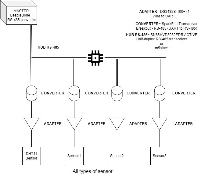
This is the structure I would like to make as you see.
A Modbus RTU communication in which the sensors act as Slave and the BeagleBone Black as Master.
I would simply need to know the pins as they should be connected in the various interfaces that I have drawn up previously.
What’s the purpose of RS485 if all of your sensors are 1-wire? How far away are your sensors from the beaglebone? Your DS2482S-100 connects to a 1-wire bus and has an I2C interface, correct? That would connect directly to a beaglebone i2c bus. I’m not experience with python, but looksl like the smbus2 library would work for talking to i2c? You can troubleshoot i2c communication with debian i2c-tools (i2c-detect, i2c-get, i2c-set, i2c-dump).
That’s assuming each of your 1-wire sensors can have a unique address.
1 Like
It’s a university project to simulate a serial link for an imaginary industry. With the budget I have available and the tools to implement the project, the basic idea is this. The sensors do not necessarily have to be 1-Wire.
Let’s say that it’s all on an experimental basis and I’m totally new in this area.
To talk to an RS485 network (multiple RS485 sensors) and 1-wire bus (multiple 1-wire sensors) from the beagleboard, you just need a single DS2482S-100 and a single UART to RS-485 transceiver. To make RS485 wiring easier, you can use the m5Stack RS485T devices. I think that total should cost less than $100.
I can’t give you specifics about wiring unless you have specifics about sensors. However, I believe your diagram above is overly complicated. You should have a single UART to RS485 transceiver between the beaglebone and the RS485 network and the DS2482S-100 between the beaglebone and the 1-wire devices.
Copied diagram for the DS2482S-100 from a page selling it:

FYI, out of the box, beagleboards can talk to 3.3V UART, i2c, SPI, digital signals (gpio), analog (AIN), Ethernet, and USB devices.
With transceivers/converters, you can talk to RS232, RS485, 1-wire, etc. devices.
1 Like
So you say something like that?
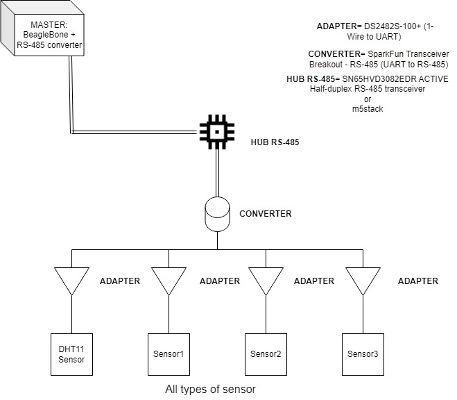
That way it wouldn’t make sense to use an RS-485 HUB, or maybe you intend to use the UART-to-RS-485 converter as a sort of HUB?? In that case, a converter that handles multiple connections would be needed, right?
For me, the important thing is that the Master-Slave architecture of the Modbus RTU communication remains consistent with what the connection between the devices is, then how I connect them is relative.
Anyway thanks for the replies, do you have any other information you can give me about what I wrote? ![]()
![]()
If ALL of your devices are 1-wire, get rid of RS485 altogether and use a single DS2482S-100 between the beagle and the 1-wire bus. If you have some requirement (that you’re not explaining) for modbus and rs485, then replace all your converter/adapter blocks with a single RS485 to 1-wire converter like this: Addressable RS-485 to 1-WIRE Converter
1 Like