BBAI-64 Cortex-R5 gpio toggle experiment

Hello All,

Expanding on @Tony_Kao’s Minimal Cortex-R5 example on BBAI-64, I would like to use the R5 core to toggle a gpio pin. I have studied @benedict.hewson’s pinmux spreadsheet and read the Beaglebone cookbook but, I must admit, I am totally perplexed as to how to connect a gpio pin to the R5 core. Does anyone have some pointers as to how to make this happen?

I don’t even know if this is possible but, I expect it should be possible.

I have the A72 cores (libgpiod) toggling pin P9_14 and can see jitter. With the R5, I’m hoping for real-time io performance.

Thanks,
Fred Eckert

1 Like

I haven’t gotten to the point in my current project where I’m working on GPIO, so I don’t yet have a self-contained sample or even definitive references. But I figure I can provide some general pointers if it’s helpful.

On hosted Linux, the BeagleBoard crew and/or TI has configured the appropriate driver to expose available ports via userspace APIs. What those drivers do internally is perform memory accesses which map in hardware to particular I/O configuration registers. E.g., logically, there’s a memory address somewhere which you can write a “1” to and it’ll set your chosen pin to a logic-level high, or a “0” and it’ll set it low. When you ask the kernel to set the pin high, it’s just writing to the appropriate memory address.

In practice, there’s some configuration the driver needs to do to tell the pin what mode to operate in – in this case, pure digital output. Other modes include a digital input, or a more specialized function like SPI or UART. Most pins have many alternate functions they can be configured for.

So, without the Linux kernel driver in place, you’ll have to do this “register-prodding” yourself. This means checking the chip’s documentation to understand which registers need to have their values changed and what those registers’ memory addresses are.

If you leave the relevant pins in the Linux device tree, the kernel might do you a favor and pre-configure the pins so that all you have to do is set their desired output value. I’d personally avoid the race condition that presents but it’s a possibility.

At a quick glance, section 12.1.2.4 of the Technical Reference Manual for the TDA4VM outlines the process of configuring a pin’s mode and setting its output state. There’s a different section which gives the actual memory addresses of the relevant registers. The process doesn’t look too bad so long as you identify the right register for your pin.

If you are looking for a simple high/low control, that’s all you need to do. If you want other types of peripherals like SPI or UART, there are other modes you’ll have to configure the pin for and more setup that has to be done. The TRM has information on that as well.

Hopefully in a week or two I’ll have at least some basic code samples that could help out here. I haven’t written for bare metal on TI processors either (only STM32s and AVRs), so I’m right there with you on deciphering the datasheets.
2 Likes

Kaelin, Thanks for the pointers!

I have confirmation that SoC architecture wise, all peripherals (except the ones in the Security enclave) are accessible from anywhere…

So, it sounds like we just need to do the following:

  1. Pinmux pins to gpio or other peripherals as desired.
  2. Ensure that Linux on the A72 side doesn’t touch the gpio or other peripherals that we want to use.
  3. Start bit twiddling.
  • Prereq: Map out gpio/peripherals we want to use (6.4 Pin Multiplexing*) (12.1.2 General-Purpose Interface (GPIO)**).
  • Option: Call out any firewalls if desired (3.3.4.2 Firewalls (FW)**).)

* Reference: TDA4VM Datasheet (TDA4VM.pdf)
** Reference: J721E DRA829/TDA4VM TRM (spruil1c.zip)

I recall somewhere I saw RCN say that TI hasn’t back-ported the BBAI64 into their SDK yet. So, it sounds like maybe someday in the future, we can leverage the TI SDK to configure the hardware. It sure would be nice to have something like the STM32 HAL (or LL) stuff for this… I am going to take a look at the TI SDK to see what it is all about.

Best regards,
Fred

1 Like

If TI has an official evaluation SDK for bare metal (or RTOS), that would be great; it would give all the needed info and some sample code for less effort.

At a glance it looks like this is what they have: PROCESSOR-SDK-J721E Software development kit (SDK) | TI.com

The “PROCESSOR-SDK-RTOS-J721E” looks like the right one.

I haven’t taken a look yet but it probably has the important bits fairly separate from their RTOS stuff.

There is a lot of code in there, including low level drivers and a FreeRTOS port. There are also some examples both for FreeRTOS and baremetal. Building everything takes a while.

However using the code in your own project is not as easy as I would like. As far as I can see there is no way to include the SDK into Code Composer to make building your own projects with the drivers easier. I suppose as long as you can build libraries, they can just be included. I have been a bit busy with other things lately and not had as much time to investigate this as I would like.

Found the physical address for GPIO0_93 (pin 9_14):

#Toggle GPIO0_93 pin 9_14 using devmem2 on Linux side:
#set  - write GPIO0 GPIO_SET_DATA45 bit 29
sudo devmem2 0x00600068 w 0x20000000
#clear - write GPIO0 GPIO_CLR_DATA45 bit 29
sudo devmem2 0x0060006C w 0x20000000

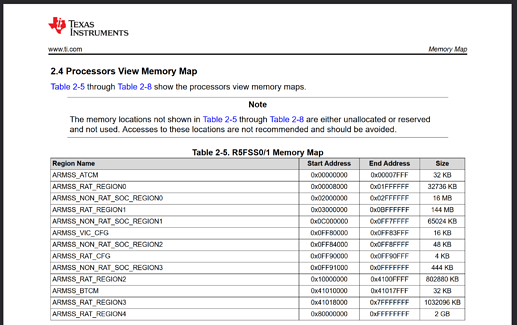
At first look, It seems like the physical address is not mapped 1:1 into the R5. Will need to investigate a bit more.

TDA4VM TRM References for further investigation:

  • 6.3 Dual-R5F MCU Subsystem
  • 8.4 Region-based Address Translation (RAT) Module
1 Like

Got it working!! Tony’s example didn’t map the entire 4G address space. Once it was mapped, the code worked.

    #define DELAY 44
    uint64_t* pSet = 0x00600068;
    uint64_t* pClr = 0x0060006C;
    for(;;)
    {
        //set the output high
        *pSet = 0x20000000;
        for(volatile int i=0; i< DELAY; i++);
        //set the output low
        *pClr = 0x20000000;
        for(volatile int i=0; i< DELAY; i++);
    }

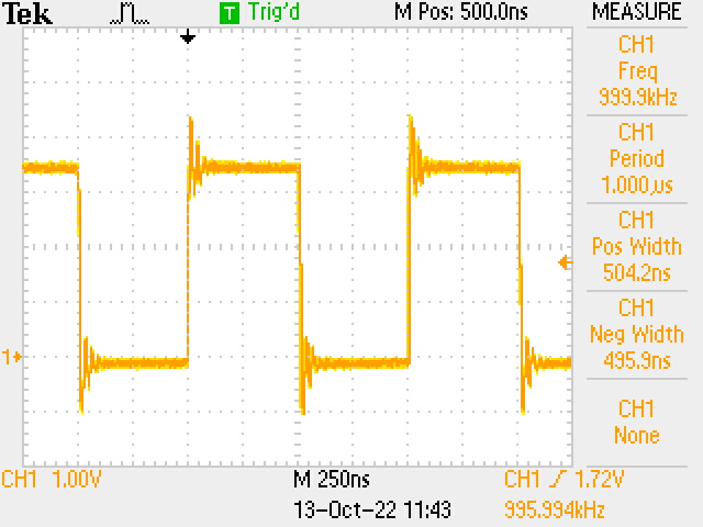
Stable square wave:
F0009TEK

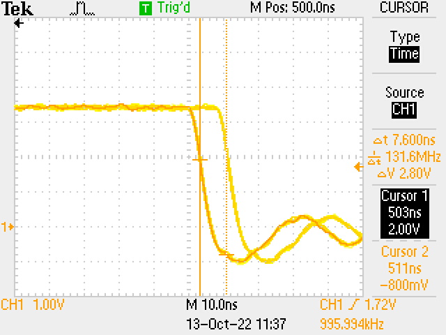
Max jitter:
F0007TEK

2 Likes

Just popping in again to mention another thing that occurred to me. One of the resources you can request in your remoteproc resource table is a VirtIO device, using the same mechanism as a virtual machine would use to access host resources. I haven’t done any investigation into which kinds of devices are supported or how they work, but there is a VirtIO device type for GPIO. It surely wouldn’t support all the kinds of I/O configurations, but it might be a cleaner way of doing I/O if all you need are the “simpler” ones.

Edit: also, there’s a latency effect involved which would need to be considered. Certainly, you lose a lot of the “real-time ness” of the R5 cores if they’re going through the host kernel every time they want to do I/O.

Also, @FredEckert, what mechanism did you use to map the additional 2G segment via RAT?

Complete 32-bit address space mapping concept came right from TI’s example:

\ti-processor-sdk-rtos-j721e-evm-08_02_00_05\mcusw\mcal_drv\mcal\examples\Dio\dio_app\DioApp.c

I uploaded an r5_toggle branch into my fork:

Fred

2 Likes

Is this example worked on beagleboard AI-64 and how to do it as I’m new to the Linux and beagleboard … I tried the sequence in the github example and didn’t work with me when trying to start the remotproc18 it replies invalid arguments … what can I do to make it work … hope you help me

Hi Michael,

The best advice I can give is to start small and work your way up. This experiment was not intended to be an example that runs perfectly right out of the box.

Perhaps you need to run the startup.sh to get it going the first time:

[/bbai64_cortex-r5_example/commits/r5_toggle/startup.sh)
executable file 6 lines (5 sloc) 279 Bytes

sudo cp test.elf /lib/firmware/
#sudo echo stop > /sys/class/remoteproc/remoteproc18/state
sudo echo test.elf > /sys/class/remoteproc/remoteproc18/firmware
sudo echo start > /sys/class/remoteproc/remoteproc18/state
sudo cat /sys/kernel/debug/remoteproc/remoteproc18/trace0

If this doesn’t do it, just break it down into small components and do each step one by one. When you hit the problem, dig in and study everything. Then debug it. If the solution doesn’t come to you, you may just need some more time to digest the information. It is a lot to learn.

Best regards,
Fred Eckert

Thanks Fred
The problem with me was the version of the Linux has to update and upgrade the factory version and then the steps you told me to make it work but had to make the optimization changed to 0 to make the toggle work .

@michael.Adel, Glad to hear you got it working. Please keep us all posted if you push further with R5 exploration.

@kaelinl, Have you gotten the chance to work with the R5 yet?? Thanks for the Virtio tip. I am about to start studying Virtio. The goal is to create the GPIO toggle pattern on the A72 core and output it with the R5 core.

If anyone has some suggestions on a good resource to learn about talking to remote cores, please let me know. Right now, I plan to use the PRU Cookbook as my intro to the subject.

Fred

1 Like

Yeah, my current state of learning is more-or-less what’s in this repo: GitHub - WasabiFan/tda4vm-r5f-rust: Sandbox for Rust firmware infrastructure targeting Cortex-R5 microcontrollers on the TDA4VM.. In short, I’m implementing a HAL+user primitives for R5 firmware in Rust without C bindings. This involves reimplementing from scratch behaviors from TI’s C HAL. I’ve implemented MPU control and will be doing the same for cache next. I haven’t done anything with I/O though. Right now the main time sinks are Rust- and reimplementation-related rather than working with the more interesting features of the chip.

I’ve been fiddling with TI’s deep learning acceleration library in the last week or two so haven’t had a chance to get back to the embedded stuff.

On the comms between the A72s and the R5s, this related document may be helpful: 3.5.3.1. RemoteProc and RPMsg — Processor SDK Linux for AM335X Documentation. It’s for the Sitara class of processors but I have to assume it applies mostly 1:1 here. I haven’t implemented rpmsg yet, so I can’t speak to more than the documentation I’ve read. I’m interested in any learnings though!

3 Likes

Related to RemoteProc och RPMsg: I learned a lot from this webinar: OpenAMP and Heterogenous Processing Project Webinar - YouTube .

Does anybody know if TI is involved in the OpenAMP project?

1 Like

@FredEckert thanks for all your generous work on this…its made it much easier for me to get started.

I was able to get your demo loaded and running, but I have 2 semi-related questions:

  • I don’t understand the relation between GPIO_SET_DATA45 and PIN 9_14 (I realize this is probably a general question). I’ve downloaded the TDA4VM docs you referenced but I’m still at a loss of how one should go about determining which GPIO_SET_DATA register / address for any given pin…for example if I wanted to move your example to PIN 8_20 - how would I go about figuring the addresses out?

  • Secondly, I notice that this example only seems to work for remoteproc18 - I tried with other remoteprocs and it either crashes the board or spits out a memory error in dmesg. I’m assuming something needs to be changed in gcc.ld file? Or is there more to it? I see this section:

__DDR_START__ = 0xA6000000; 

MEMORY
{
  TCMA (rwx) : ORIGIN = 0, LENGTH = 0x8000
  TCMB (rwx) : ORIGIN = 0x41010000, LENGTH = 0x8000
  /* MSRAM (rwx) : ORIGIN = 0x70000000, LENGTH = 0x40000 */
  DDR_0 (rwx) : ORIGIN = __DDR_START__ + 0x100000, LENGTH = 0x1000
  DDR_1 (rwx) : ORIGIN = __DDR_START__ + 0x101000, LENGTH = 0xEFF000
}

Is this what determines what remoteproc it will run on? If so how would one go about finding what other addresses correspond to the various other PRUs?

Sorry to send so many questions, but I’m trying to learn this and its a bit above my paygrade at the moment…

I can’t comment on point (1), but regarding point (2):

Note: you said “PRU”, but this is code for the R5F cores and not the PRUs. Some similar concept apply but the ISA is very different.

Yes, some of this is specific to the core. As I understand it:

All addresses shown are virtual addresses in the R5 core’s address space.

The two TCMs (“tightly coupled memory”) are a part of each core – i.e., the R5SS0 complex has two cores, 0 and 1, and each has an A-TCM and a B-TCM. And there are two of those complexes, R5SS0 and R5SS1. Since every core in every complex has one of these, they show up in the “same place” in the memory map for all the cores. The linkerscript can load the data into the same place no matter which core it’s on, the addresses are the same from the core’s perspective. The specific addresses come from here in the TRM (Technical Reference Manual):

Then there’s DDR (RAM). The RAM is shared between all core – is not core-local – and thus their address space is shared. I haven’t looked deeply into the address translation (RAT) defaults, but the physical RAM is mapped somewhere in the 0x80000000+ range. Out of that, the configured device tree chooses which regions to allocate to the individual cores. The device tree defining this region is here: src/arm64/k3-j721e-rtos-memory-map.dtsi · v5.10.x-ti-unified · BeagleBoard.org / BeagleBoard-DeviceTrees · GitLab

So you could update the address to be the memory region for one of the other cores.

Note also that there may be conflicts with existing firmware running on other cores, since the EdgeAI DTS is primarily designed to run their coprocessor firmware.

1 Like

@kaelinl many thanks for that explanation it is very helpful (also, yes I mistakenly said ‘PRU’ but meant R5F…I’m also studying those so had PRU’s on the brain…).

What you’ve posted really helps clarify things. So, given above example, 0xA6000000 is the start address space for r5fss1_core0_dma_memory (per the device tree specification), which is then further subdivided into DDR_0 and DDR_1. Any ideas on how / why those DDR regions were chosen as such?

Further, in the linked dtsi file, there is also a reservation for the same core named r5fss1_core0_memory_region…so each core as “dma_memory” region and also a “memory_region”…I wonder why?

The memory-region property here: src/arm64/k3-j721e-rtos-memory-map.dtsi · v5.10.x-ti-unified · BeagleBoard.org / BeagleBoard-DeviceTrees · GitLab

Is documented here as:

memory-region:
  description: |
    phandle to the reserved memory nodes to be associated with the
    remoteproc device. There should be at least two reserved memory nodes
    defined. The reserved memory nodes should be carveout nodes, and
    should be defined with a "no-map" property as per the bindings in
    Documentation/devicetree/bindings/reserved-memory/reserved-memory.txt
  minItems: 2
  maxItems: 8
  items:
    - description: region used for dynamic DMA allocations like vrings and
                    vring buffers
    - description: region reserved for firmware image sections
  additionalItems: true

The entries in the memory-region list are ordered, so e.g. vision_apps_main_r5fss1_core0_dma_memory_region is the “region used for … vrings and vring buffers”, while vision_apps_main_r5fss1_core0_memory_region is “region reserved for firmware image sections”.

In other words, 0xa6000000 is the start of the DRAM region but the first 0x00100000 bytes of it are reserved for data that the Linux kernel injects into the processor’s address space for communication between Linux and the firmware. “Free use” data starts at 0xa6100000. For this specific core.

I don’t know why Tony chose the names DDR_0 and DDR_1. But as far as I know, that subdivision is purely a user/firmware dev choice and the rest of the system doesn’t care. Both are part of the “non-DMA” normal data portion mentioned above.

The DDR_0 region is used for the remoteproc resource table. It is defined as one page (4096 bytes) probably just for convenience. See here for some info on the resource table. It’s the way that the firmware exposes metadata on the system resources it needs, and also how the kernel “replies” (one-time, on core load) by writing data into empty spots in the table. In other words, the resource table is the way the firmware tells the kernel what to put in that reserved “DMA” region we discussed previously.